Copyright © 2007 - 2025
Copyright © 2007 - 2025, Coachworks For contact data Click
Here. ![]()
This engine has been sold, but the page has been retained for reference purposes.
 Porsche
Engine: Un-Numbered, Two-Piece Case 356 Type 546, 1500cc
Porsche
Engine: Un-Numbered, Two-Piece Case 356 Type 546, 1500ccThis engine was completely rebuilt as outlined on this page.
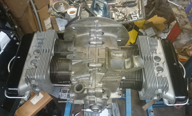
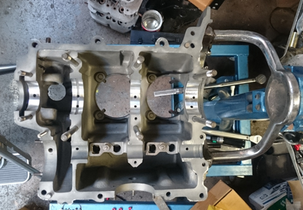
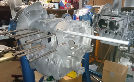
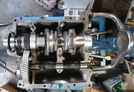
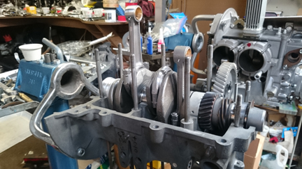
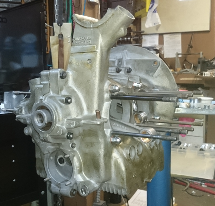
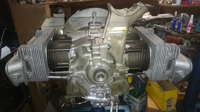
AT RIGHT: This engine as a long-block. Almost ready to run! Following this image, the engine was fitted with loaner parts and run-in on the dynamometer as pictured below.
Note that the run-in process is performed on our Stuska Water Brake Dynamomenter, as per Porsche factory specifications as outlined in the Workshop Manual, "Running-In and Testing" operations, 43 EN and 44 EN, pages E51 and E52.
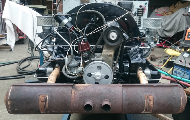
AT RIGHT: This engine on the dynamometer. Yes, there's a great deal that's "wrong" with this engine! The only parts here that are going with this engine is the "long block" as pictured above. All the other "completion parts" - sometimes called "accessories" - are on loan so that this engine can be run-in as described in the above text.
This Porsche 356 type 527 engine (1500cc) is has just undergone a complete overhaul, and is fully balanced for smooth running, long life, and a few more HP. The purpose of this page is to document the steps used in assembling this engine
The crankcase is "numbers matching" and is in very good condition. The expression "numbers matching," when it comes to two piece crankcases, simply means they were manufactured together as a pair and remain so.
The crankshaft has been upgraded to the "B" series, which are less prone to cracking. It is fitted with new, original-size pistons and cylinders.
Every detail about the engine has been attended to, as outlined below; nothing was overlooked. If something isn't clear or has for some reason not been documented, please contact us.
In the interests of both brevity and accuracy, I / we have been interested in these engines since the late 1970s and have been collecting parts. ...After a while, some of the bits get confused with one another. So, we really haven't got anything useful about the older history. The heads that were originally with this case when I / we got it are possibly the pair that are going back on it, but there's no certainty of this - they do appear to be a matched pair, however! Note that the case is a "replacement case", provided by Porsche as a new part to repair some malady, and as such it has no serial or type numbers stamped into it; it was cast in the spring of '53. Note that the use of this replacement case was purported to be for a '51, so that's why this literature makes that statement. There is no practical difference between the two longblocks other than date of the castings between a 527 from 1951 and a type 546 from 1953 as the only significant difference is the fitment of Solex 40s on the '51 and 32s on the '53.
The first thing to do was clean the crankcase. To do a proper job in this era of weak solvents that don't really do the job, this means that the case had to be gently media blasted. And that means that the "soft plugs" in the crankcase all had to come out for proper cleaning of all media out of the case to ensure no media remains behind to contaminate the engine later.
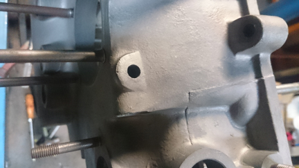
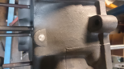
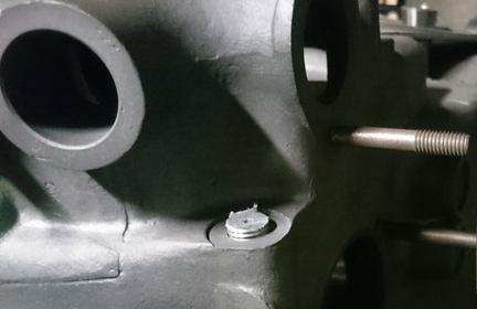
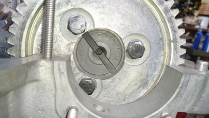
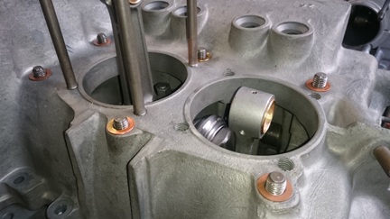
BELOW, LEFT & RIGHT: Here one of the several "soft plugs" can be seen removed on the left image and installed on the right - the plug itself is that silverish disk seen on the right image. As noted in accompanying text, all the soft-plugs had to be removed in order to ensure there was no debris left inside the oil passages. The reason it looks so silver is because it's actually aluminum whereas the crankcase is mostly magnesium.
Following this, the case was thoroughly examined and any issues addressed. This case had a few "remedial issues" to deal with. One such issue was that the crankcase required an "align bore", which is to be expected on a case this old. (I didn't take any photos of this case being align-bored, but there's a good image or two showing the align-boring equipment in use on this page.) Afterwards, a trial fitting of the bearings is performed.
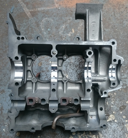
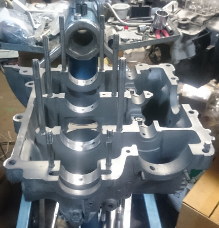
BELOW, LEFT & RIGHT: The case here has been cleaned and "align-bored". This is an interesting crankcase because it tells us something about when a casting change was made - and there were many casting changes through this period! The left case half and right case half have different "webbing", or internal support. Note how the inside of the head stud bores are supported by extra material in the right half (right image) and are not supported with that extra material in the left half. ...Yes, I tripple checked, the two halves belong together!
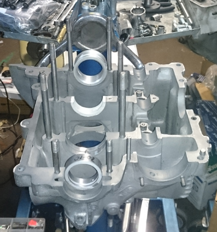
BELOW LEFT & RIGHT: A small bit of repeat is the image at left below - just the align-bored case from another angle, however, in this image you can see, if you know where to look, that at least two of the soft plugs have not yet been installed. (Look in the nose area, "below" the fuel pump. In the right image, the bearings are installed to ensure no surprises later.
 Another
issue was that the threaded bore that receives a steel fitting to pass oil up
to the bypass oil filter and which also provides the mounting point for the
oil pressure switch had been opened up to receive the equivalent part from the
later 3 piece crankcase era.
Another
issue was that the threaded bore that receives a steel fitting to pass oil up
to the bypass oil filter and which also provides the mounting point for the
oil pressure switch had been opened up to receive the equivalent part from the
later 3 piece crankcase era.
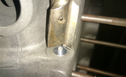
AT RIGHT: Here, an aluminum rod has been threaded and inserted into the enlarged bore as a first step to "un-doing" this "upgrade!" (See accompanying text.)
This modification makes it possible to run the very nice "oil junction block" that adds in a convenient spot for an electric-type oil temperature sender. However, our plan was to go old-school, so this now larger-threading had to be returned to the stock bore and thread pitch. This was accomplished by threading a bit of aluminum rod, threading that into the bore, then "facing it off, followed by tapping the insert with the correct size thread.
BELOW, LEFT & RIGHT: Here, the aluminum rod has been cut off. Note that a small guide or pilot hole had been drilled into the rod on the lathe during the threading process. This was to provide an easy centering for later on the mill table. At right, the spot-facer has been applied, but the cut was inturrupted to confirm centering. (The spot-facer has the ability to run a centering drill but which we elected not to use here which is why it left an area un-cut.) You can notice that the centering was perfect! The image doesn't really do the centering effort justice - it was truly dead-center. ...A few moments later, the spot-facing operation was completed as can be seen in later images below.
 Finally,
the pilot hole was drilled through and new threads were tapped.
Finally,
the pilot hole was drilled through and new threads were tapped.
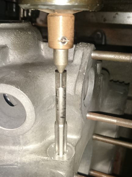
AT RIGHT: As described in the text, here the aluminum insert is threaded on its inside bore back to the original thread diameter and pitch. Once centered, the mill table and work piece were left aligned while bits were changed, first from the spot-facer to a drill bit, then, seen in this image at right, a spring-loaded centering bit is used to keep the tap in perfect alignment. The tap is turned by hand to cut these threads! The result was a perfect repair.
Another issue with this crankcase was that the oil pickup tube had become bent out of position. This was fairly easily rectified and finally, it was ensured that the pick up tube is secure in the case. Just as a "belt and suspenders" exercise, a bit of sealant was applied to the joint of the steel pickup tube into the case to help ensure there are no air leaks.
Not forgotten, the cylinder "decks" were checked that they are in one plane with their immediate neighbor using a special tool designed just for this purpose. And, there's a reason for thorough checks like this; in this instance, both halves had a low-spot of between the cylinders. Cylinders 1 & 2 were low in the center by about exactly three thousandths of an inch while cylinders 3 & 4 were low by a little less, at about 0.0025" - very common situation for these older magnesium cases. The specification is 0.1mm, or, about 4 thousandths, so they're within specifications.
Finally, the rear-most two threaded bores, the ones that accept the forward pulley shroud, had a "bottoming tap" run through them. These threads are a weak spot because they are often stripped by fools who over-tighten the bolts that run in them and the use of too-short fasteners doesn't help. So, I cut a few more threads just to ensure there's no problem later. (Long M6 bolts should be used here - which is good advice anyway.) And, unusually, all of the sump studs are in great condition!
 As
cited above in the background section, no crankshaft or rods yet remained with
the case. It happens that the early "pre-A" (and even A) crankshafts
are more prone to breaking than the younger cranks are. So, I selected a "B"
series crankshaft for this engine because of the cracking problem with the older
ones. As with all engines I / we build, the crankshaft was magnifluxed to check
for cracks. Finding none, it was reground to first under on both rods and mains
(nominally 49.75mm, and 52.75, respectively) which means, all other things being
equal, it's about exactly one third through its total service life.
As
cited above in the background section, no crankshaft or rods yet remained with
the case. It happens that the early "pre-A" (and even A) crankshafts
are more prone to breaking than the younger cranks are. So, I selected a "B"
series crankshaft for this engine because of the cracking problem with the older
ones. As with all engines I / we build, the crankshaft was magnifluxed to check
for cracks. Finding none, it was reground to first under on both rods and mains
(nominally 49.75mm, and 52.75, respectively) which means, all other things being
equal, it's about exactly one third through its total service life.
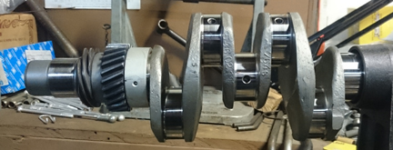
ABOVE RIGHT: The crankshaft mounted in the crankshaft stand, polished, bearing 3 and gears mounted, awaiting rods.
 Of
course, after magniflux, it was thoroughly cleaned and the journals polished
it.
Of
course, after magniflux, it was thoroughly cleaned and the journals polished
it.
I then pulled out a set of already rebuilt rods, mounted the crank in the crankshaft stand and installed the rods.
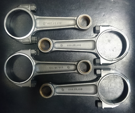
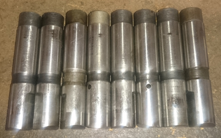
AT RIGHT: Here are the rods, serviced as described here, ready to be installed.
For me, "rebuilding the rods" means to:
 Back in
the early 1990s I got a large stash (about two dozen) of new camshafts for two-piece
crankcase engines from Ritchie Lukes. So, I dug one out for this engine. This
particular one had been ground by his friend Dema. I think a new camshaft is
a nice touch!
Back in
the early 1990s I got a large stash (about two dozen) of new camshafts for two-piece
crankcase engines from Ritchie Lukes. So, I dug one out for this engine. This
particular one had been ground by his friend Dema. I think a new camshaft is
a nice touch!
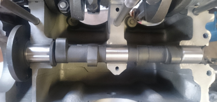
AT RIGHT: This cam, laid in the case. Yep, it's brand new!
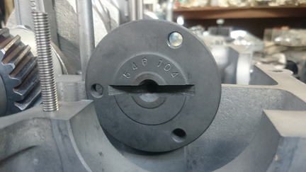
BELOW, LEFT & RIGHT: Here we see the end, with and without gear. The number on the end is Porsche's own number for this profile. It just happens that the gear that fits with proper lash happens to be a new gear. And, why not? Yes, new bolts, too.
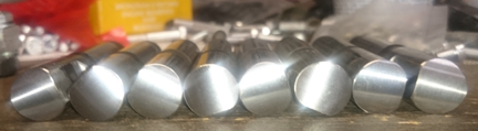
ABOVE LEFT & RIGHT: These lifters, refaced and polished. I hadn't noticed until I posted the image at right that the oil coating to protect them in storage should have been wiped off before taking the photo! Oh well...
In early engines like this one, the lifters are added after the engine is otherwise completed, just before installing the rocker arms... They're shown here because they're usually shown with the camshaft.
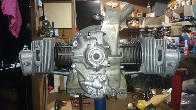
One the crankcase preparation was complete, the crankshaft assembled, and cam gear selected - as described above - it's almost done! Here, the left half is completely ready for assembly.
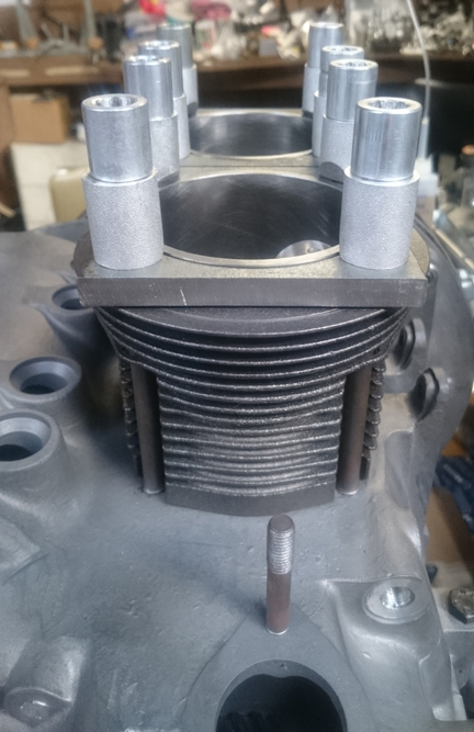
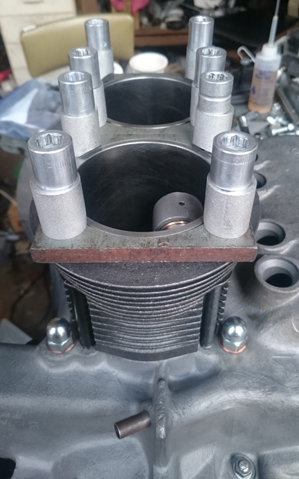
BELOW, RIGHT & LEFT: Here, left, sealant has been applied and the copper sealing washers (damned expensive these days!) are fitted awaiting the acorn nuts! Then, at right, the acorn nuts - BEAUTIFUL ones! - have been threaded on and torqued. Along the way, the four missing head studs for cylinder 2 were installed! Three of the 4 studs, especially the one in the foreground in the right image, are freshly re-plated while the rest aren't, and this is why these studs look black.
At this point I got a little ahead of myself. One chore I could have but didn't do earlier on was to replate the crankcase! Recall that it has been media blasted. That removes all the protective coating! Well, as I learned on this other two-piece crankcase 356 engine, which you can read about here (there are comments on the plating of the case throughout this page), you can apply plating at any point (even when it's fully assembled!) BUT it makes most sense to apply it at the short-block stage because to apply it earlier will use a lot more product, and using it later is more challenging because of how the process works; at this point, the surface area that needs coating is still relatively easy to get to!
...As I said, I got a bit ahead of myself... So, some of the images here are out of order because I back-tracked back to a short-block to get the plating process done!
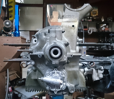
...And here is the engine as a short block, but plated.
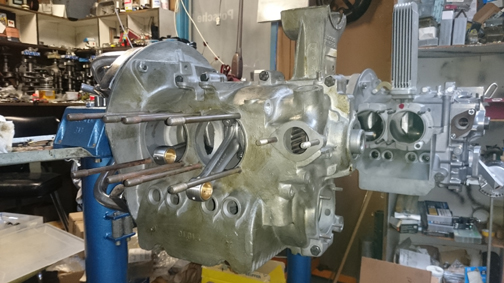
ABOVE, LEFT & RIGHT: This case took the plating a little more darkly than some do. It's a little splochy and that's just a part of the nature of the beast. Actually, the photography doesn't do it justice and accentuates the splotchiness; both sensitivity to lighting and the red component in the brown affect this.
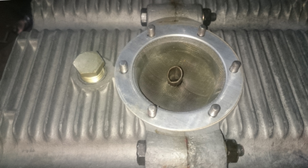
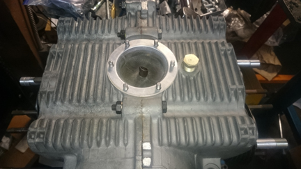
BELOW, LEFT & RIGHT: Here you can see that the caes bottom is in pretty good condition, too - not all corroded and pitted from sitting in moisture for decades! And, a new sump screen was fitted - seems only natural! Also, a sweet drain plug was mounted, too.
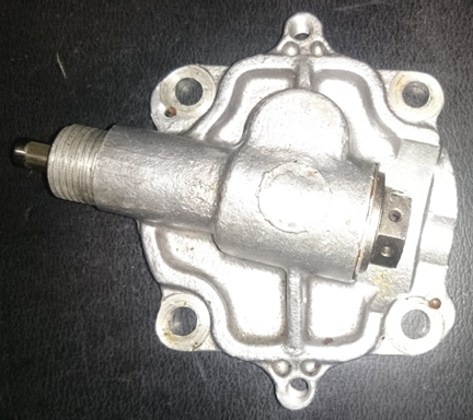
Now, the oil pump. Not all the images turned out - in particular, the flash made the shots of the gears unuseable. However, here are the several good images.
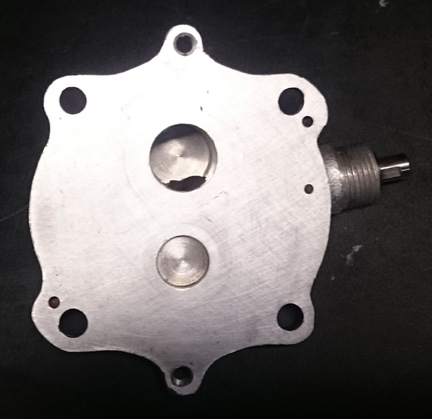
BELOW, LEFT & RIGHT: The oil pump cover, inside and out. The inside surface was faced off by laying a sheet of abrasive on a sheet of glass and gently "sanding." Then, of course, it was cleaned and a new seal applied.
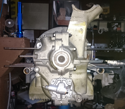
BELOW, LEFT & RIGHT: Here's the completed short-block, with and without flash turned on! Notice how the color changes dramatically! The in-person experience seems to be somewhat between the two, if you asked me!
Shortly thereafter, the oil control piston, spring, and retaining cap were installed.
 Time
to install the Pistons and Cylinders.
Time
to install the Pistons and Cylinders.
At this point, I had a decision to make as I had the following options:
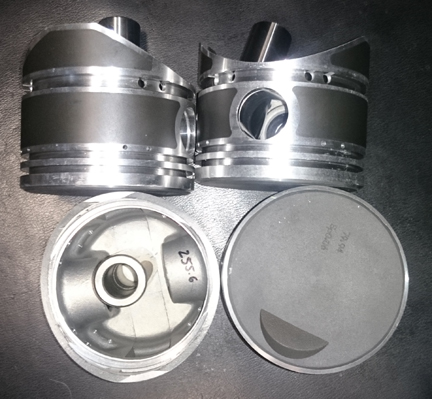
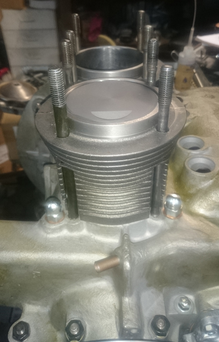
After talking with a number of people, I settled on the new set - one piston and cylinder pair is imaged at right. (However, if you prefer an alternative choice, I can accommodate that for you - the heads can always be taken off and a different set fitted, so lets talk about that if that's what you want.)
AT RIGHT: The pistons (and their cylinders) are the new modern reproduction. I've used them in close to a dozen engines so far without any problems. They're nominally 80mm in diameter, as stock. They're also fairly light-weight as such parts go - the pins make up more than a third of the total weight!
In my view, while the stock specification for weight-differential in the pistons of early engines is something like 16 grams, if I recall correctly, piston weights need to match very closely in any single set, and I strive for 0.1 gram. This set was out by only about one and a half grams - not too bad for a standard production tolerance for a cast set. (Many high-performance builders say within one gram is fine - but the closer the better.) Mixing-and-matching pins to a better combination got the difference down to 1 gram. There were two pistons of nearly identical weight, and one heavy and one light. Rather than bringing all three of the heavier ones down to the weight of the lightest one, I merely trimmed the weight from one piston and got it to the mid-point between the two that were closely matched. So there's one that's a bit light and the total spread is 0.6g - plenty good enough! This engine might see 5000 rpm, but it won't see 6000!
New parts are not exempt from careful checking!
We always check the match pistons to cylinders and match piston weights as a set, and provide any remedial action to correct any errors before installation. For example, by shuffling around the piston pins among the pistons, one can usually improve the matching of piston weights. This set naturally balanced (without removing material) to within 0.2 grams.
For many shops, from this point, installation goes very quickly, but we think this is where one needs to take one's time! The key reason one needs to take time here is that there are production tolerances on every part in an engine, and while a set of parts may look identical, there's often subtle variation between members of a set, and there are sometimes significant errors in production that weren't caught by the manufacturer's quality control processes. These errors can "stack up" and cause problems if not discovered and corrected.
Here's our process: Two of these steps require special tools most shops don't have.
We like to carefully measure everything and then mix-and-match the parts for superior fit. We have also discovered significant manufacturing errors with this process which would likely have gone unnoticed without these measures. It is remarkably easy, for example, to overlook the circumstance of the crankshaft bore not in the true center of the crankcase, angled on the horizontal left or right of center, or not on the same horizontal plane at all. Yet examples of errors like these are not as uncommon as we would like.
The height comparison check (visible below) is done to ensure that there are no differences between the cylinder heights that the head itself "sees." The book value for tolerated error is 0.1mm (four thousandths of an inch), and in this instance, both sides had one of the edges just barely within limits. On both sides, the low spot was the inboard edge of the rearmost cylinder. However, they were within specification and it's especially important to check.
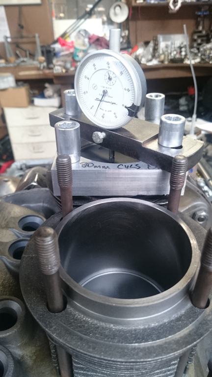
BELOW LEFT & RIGHT: Here we see the Cylinder Height Check - the "CHC" - being performed on both sides, left is cylinders 3 and 4, right is cylinders 1&2. What can't be seen here is the straight edge that's laid across the edge of the cylinders. We use a large block of aluminum for this job and it nearly fills the gap, right to left in these images, between the studs and so wouldn't make a great photo!
By the way, it's hard to see in the images above but the cylinders are in fact not touched on the surface that seals with the cylinder head by the clamping forces. The spacers between the head nuts and the retaining flanges are under cut so they don't touch the head. If you look at the studs & spacers in the background this becomes more clear.
 The
second special tools are used for...
The
second special tools are used for...The next thing we do is something nobody else does (that we know of) in the engine building process, and that is to measure the height the piston crown comes above the plane of the top of the cylinder. I call this the CAC, or "Crown Above Cylinder." This value is important because, firstly, it can reveal deeper problems, and because it helps us get the compression ratio equal in all four cylinders.
AT RIGHT: The special tooling discussed in the text is used here on this engine to measure the distance the piston crown reaches above or below the top of the cylinder - the CAC or Crown Above Cylinder (as is usually the case on 356 engines). Each piston and cylinder pair is so measured and from this, as described in the text, either the parts can be moved around or modified as necessary to effect a more perfect assembly.
Here are some of the deeper problems that can be discovered through a CAC check:
In order to do this for these engines, you have to have special tools. Here, you can see them in action in the image at right.
Even if you can't read the needle in this image, the distance between the smallest tick marks is one hundredth of a mm, or 0.0004" - LESS than half a thousandth of an inch - and you can discern to perhaps a tenth of that! So, this is a very accurate measure, performed while the cylinder is under torque, so any shims are squished flat, etc.
The accuracy is so good, that if you take the time to swap parts around, you can accurately determine discrepancies in the manufacture of the various parts even if you can't measure the parts accurately enough individually! But, we ARE splitting hairs here! However, a benefit to both engine builder and customer is that the ability to move parts around for better fit means that perfection is more easily achieved, and the more equal the HP production of each cylinder, the smoother the engine will run, the more HP the engine will produce overall, and the longer the engine will last in service.
Because this process includes the entire assembly, torqued as in service, and measures the height each piston protrudes out of its cylinder, all errors in connecting rod lengths, cylinder heights, crankcase spigots depths (cylinder bore deck), piston connecting pin heights, and shim thickness' are accounted for in the measurement results. There is no superior method.
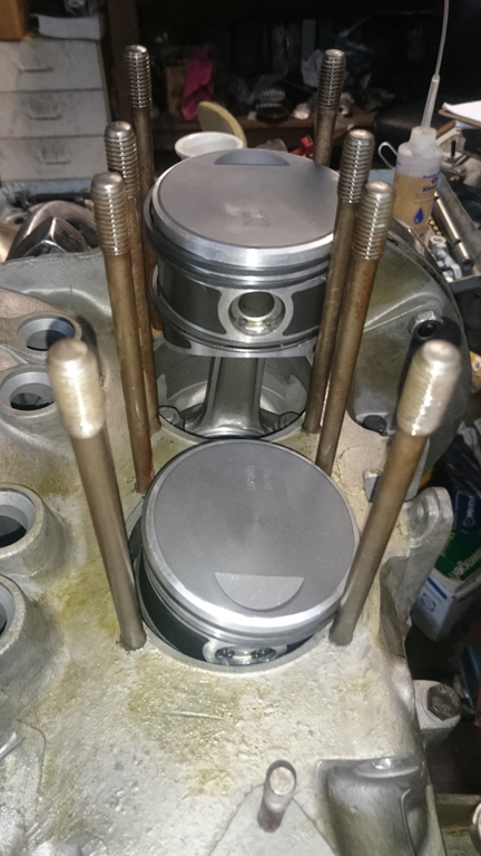
Eventually, all the cylinders have been trial fit and measured, etc, and you're left like this, ready to know what the combustion chamber volumes are inside the cylinder heads so you can shim the cylinder bases as appropriate to match the compression ratio right-to-left.
These heads are in great condition and, remarkably, it does appear they were actually originally paired together from new! The guides were of the 10mm variety, but they still had bronze seats in them. (Bronze seals well but wears out quickly. Also, bronze can't take the unleaded fuels we have today.) The only flaw I found was one crack in a lower fin. I welded up the crack and smoothed it off - you can see the result in the lower head below left.
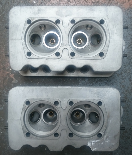
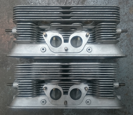
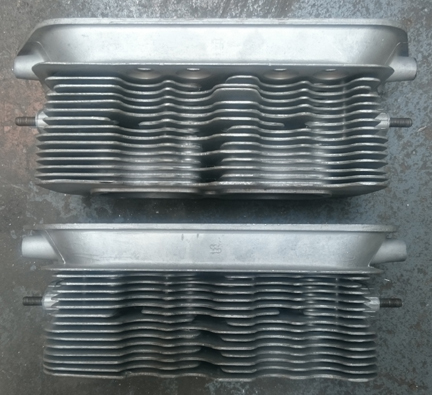
ABOVE, LEFT & RIGHT: These heads, combustion chambers showing new seats and guides, are in great condition, and the top view showing no broken fins at all. All good studs, too. However, you can see where I welded up the one cracked fin in the left image here, on the right hand side of the lower head.
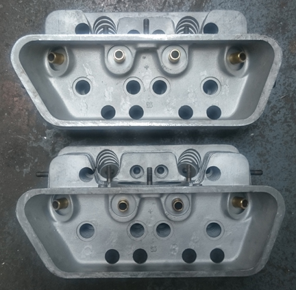
RIGHT & BELOW RIGHT: The rocker chambers are in similarly great shape, and again the new guides are visible. And the head bottoms - once again, no broken fins... And, in all these images, note how clean these heads are - no ancient dirt impeeding cooling.
The heads were washed with the aqueous parts washer, then media blasted clean. Then the machine work was performed, the seats ground, they were washed again, blown clean with compressed air, and then carefully assembled.
New seats were installed all around. And, while at it, all new guides were installed, too. That's very easily said, but very hard to do correctly! The reason is that the specifications book lists three different setups, and none of the parts are readily available anyway. So, you have to carefully measure what system is presently installed - and this many years on you cannot trust that all the guides or seats are of the same type! The valve guides and seats had to be made for these purposes "from scratch." (Pretty useful stuff, that scratch!)
I didn't think to take any photos before working on them, so the photos begin above with the guides and seats already installed.
The valves were all cleaned, refaced and polished. And of course, the valve seats were ground (after the above photos were taken).
 It
was decided to use single springs instead of the original dual-springs, as provided
for by Porsche. It turns out that there were THREE different versions of the
valve setup in the two-piece crankcase era, and 6 in total! When I first began
rebuilding these engines some decades ago, the springs were already long ago
not available, so I began an effort to figure out a great solution for our modern
era. I did my work in combination with some great tooling to measure spring
tensions and spring dimensions and then experimented some, knowing the official
specifications - spring rates, heights, wire diameters - and working with a
few surviving examples in great condition, and the weights of the materials...
This is vital because the early setup, with "radius lifters", are
very succeptible to extreme wear resulting from too-high spring pressures, yet
the valves may float if it's not high enough. The result is that I now can source
new springs that closely match the originals. ...I think we're the only workshop
in the world who's gone to this much trouble! But we care..
It
was decided to use single springs instead of the original dual-springs, as provided
for by Porsche. It turns out that there were THREE different versions of the
valve setup in the two-piece crankcase era, and 6 in total! When I first began
rebuilding these engines some decades ago, the springs were already long ago
not available, so I began an effort to figure out a great solution for our modern
era. I did my work in combination with some great tooling to measure spring
tensions and spring dimensions and then experimented some, knowing the official
specifications - spring rates, heights, wire diameters - and working with a
few surviving examples in great condition, and the weights of the materials...
This is vital because the early setup, with "radius lifters", are
very succeptible to extreme wear resulting from too-high spring pressures, yet
the valves may float if it's not high enough. The result is that I now can source
new springs that closely match the originals. ...I think we're the only workshop
in the world who's gone to this much trouble! But we care..
Of course, not just the spring, but the installation is vital. Just as with other engines I build, the springs are shimmed where the valve and retainer are position specific, and where the strongest springs (there is always some variation) get the heavier (intake) valves. This is done so that all the valves float at the same time and thereby give a good signal to the driver to back off!
Now, we mount the heads and finish off the long block. We first use our data on combustion chamber volumes and CAC (Crown Above Cylinder) data and calculate out which side each head should go on and what shimming should be used to end up with what compression ratio. It should be noted that this engine has an exactly stock compression ratio of 7:1.
 Now
that we finally know where everything goes, work progresses at a good pace -
at long last! Mount the rings, hang the pistons, slide the cylinders on, put
the lower cylinder shrouds in place, then the pushrods and mount the heads!
Now
that we finally know where everything goes, work progresses at a good pace -
at long last! Mount the rings, hang the pistons, slide the cylinders on, put
the lower cylinder shrouds in place, then the pushrods and mount the heads!
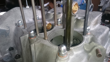
AT RIGHT: This engine, about to get its cylinders installed. The distributor fitted is there to keep the distributor drive gear in position and does not come with this engine. It is, however, a correct 383 unit..
Yes, normally the distributor drive shaft would not have been installed. This is because it should be left out until a distributor will be (and stay) installed because otherwise, if anyone rotates the engine backwards, the drive gear will ride up on the bronze crankshaft gear and may damage it. However, on two piece crankcase engines, the cam is harder to see through the sump hole and just to ensure there's no error, the distributor has been mounted so that the valves can be adjusted following installation of the heads.
For a flywheel, I went with an original one with 180mm clutch surface mated with an original 6 spring pressure plate.
BELOW LEFT AND RIGHT: The mounting of the pistons and cylinders.
...And a few minutes later, we have this:
The valves were adjusted, wire bails attached and the valve covers mounted.
See the two images up top for more of how it looks complete.
I decided to go-ahead and run-in this engine. So, I mounted up loaner completion parts that do not come with this engine, mounted it to the dynamometer and ran it in!
Yes, this image is the same one we see way up near the top!
Of course, note that the run-in process is performed on our Stuska Water Brake Dynamomenter, as per Porsche factory specifications as outlined in the Workshop Manual, "Running-In and Testing" operations, 43 EN and 44 EN, pages E51 and E52.
NOTE: If this engine is sold as a long-block... One should NOT install the distributor drive gear without also installing a distributor because if anyone rotates the engine backwards, it will push the drive gear up where it can damage the bronze drive gear! Therefore, the distributor drive is NOT mounted until the last reasonable moment!
When you're ready for work on your machine, just let us know.
Because some people are keeping logs of VIN and engine numbers and then purport to tell people what someone else has, out of respect and concern for a buyer's privacy, exact VIN and engine number data are not published here.