Copyright © 2007 - 2025, Coachworks For contact data Click Here.
Copyright © 2007 - 2025
Copyright © 2007 - 2025,
Coachworks For contact data
Click Here.
![]()
I've had to do this repair a few times and have seen crankcases scrapped because of this problem, so I thought I'd help by showing how it's properly repaired.
![]()
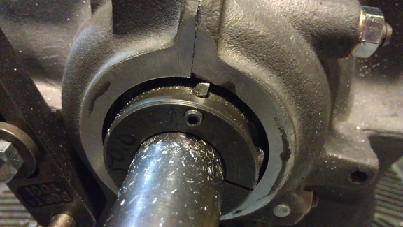
Note that it's vital the pulley bore be in perfect alignment and
concentricity with the crankshaft bore!
(For more on this topic, see this page.)
 What you
need
What you
needIn addition to the crankcase to be repared, you need some basic machine tools, though an ingenous persion may be able to devise ways of accomplishing these things with lesser tools. I'll leave all that to you - here's what I use:
These engines utilize a cooling fan and generator that are powered via a belt driven by a pulley mounted on the crankshaft - the "crankshaft pulley". Instead of providing a grease or oil seal, VW and Porsche utilized a system that runs what's called an oil return thread in close proximity to an outer surface - the pulley's bore in the crankcase - and surface tension of the oil touching both surfaces at once draws the oil back into the crankcase and away from the outside world.
However, when the main bearings begin to age and wear, the pulley's return threads can actually touch the crankcase and make the bore larger.
When it wears a lot, it can lead to leaks at the pulley and it also prevents the crankcase from being "Align Bored" - a process by which the main bearings may be renewed in a larger size. Performing an align-bore on the crankcase is a natural part of the crankcase's service life. (Given the original "standard" size, there are a total of four bearing sizes giving potentially three major overhauls in the engine's life.) If you can't fix the pulley bore, you can't align-bore the case and that may mean you can't re-use the crankcase. And that's very bad if it's valuable for some reason!
 The
Weld
The
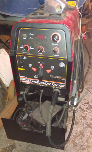
WeldThe first step is to clean the area and then weld on more magnesium, for early cases, and aluminum for later cases. This is usually done with a TIG welder using argon as the shield gas because the correct magnesium wire for MIG machines is outrageously expensive and very hard to find, and magnesium can't be welded with oxygen / aceteline or older methods like forging.
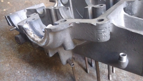
The preparation is as for any weld - no need to cover all that here! Good clean metal is required. I do recommend taking off a bit more metal than just what's needed to make it clean. The reason is that you'll likely have some porosity problems at the interface between the older crankcase material and the filler material, and if you grind a way a bit more, this porosity will be locked up inside the case instead of being at the finished serface level.
Let me tell you, welding magnesium is a lot harder than any other metal you're likely to find need to weld in a Porsche or VW workshop! It's quite a bit harder than doing aluminum, and the filler-rod is outrageously expensive! As in, you don't really want to know - I sure didn't! However, I'm getting better with practice!
Note in the image above right how the pulley bore is already welded. Try to keep the new material out of the plane of the case halves, where they join.
 Facing
the Crankcase Halves
Facing
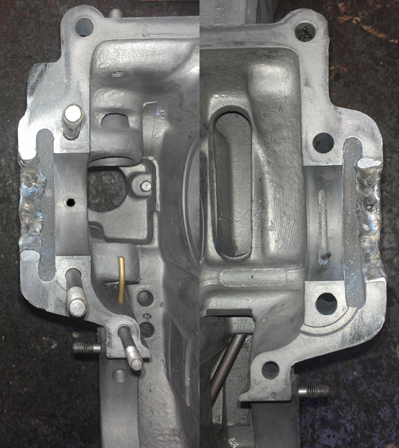
the Crankcase HalvesAt right can be seen the two halves welded up and already "faced."
In this process, weld material that extends across the plane of the crankcase half seam is removed. This is vital so that the case can be bolted together once more! However, take out too much material and a leak can develop. Perfection is desired!
In my approach, I use tape to protect the adjacent areas of metal while I take down the majority of material and get it close to the plane. The tape will get filed off if one continues but I then take the tape off because it clogs the file.
The last bit has to be done VERY delicately.
I recommend a sharp, new file for the first phase, where most material is removed, and then switching to a dull file to finish it off!
 Boring
Bar Support at Bearing Four
Boring
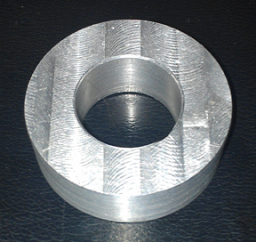
Bar Support at Bearing FourFor this next phase, you need to fabricate a piece of aluminum that fits the crankcase exactly as if it were a bearing to fit main bearing number four.
The outside dimater must be larger than the existing bore for bearing number 4 (the "nose bearing"), just as with an actual crankshaft bearing, so that it "crushes" into the case for a proper fit. Use the specifications book to get the right data for your engine, however, if the crankcase needs an align-bore, be careful to make a tool that fits bearing four as it is now, not as it will be after an align-bore!
The inside diameter must match the requirements of your boring bar. I use a Port-A-Tool brand boring bar and it uses a nominally one inch bar. The fit needs to be as good as you can get it. I usually shoot for ONE thousandth of an inch clearance.
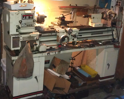
This is straight-up machine work. There are several ways to do this, but in my case, I started with a thick plate of aluminum, cut out a chunk big enough on my band saw, then drilled an M8 through-hole with a 1/2" step. This bore and step are so I can fit it onto a special holder I made that lets me mount t in the lathe easily. I then turned the OD.
I then remove the part from the special holder and chuck it directly into the lathe. This makes it easy to turn the ID to size.
This work isn't so critical because if you blow it, you can always start over with a new chunk of aluminum!
I now have two of these because I've had to do this procedure several times to save valuable crankcases.
 Face-off
external weld material
Face-off
external weld materialThe next thing to do is to install the boring bar support bushing into bearing 4 position and bolt up the crankcase. Install the bearing now to avoid having to back-track, and because it's easier to center on a smaller bore. You might even have a one inch mill or other tool that fits your milling machine's quill, making centering up even easier.
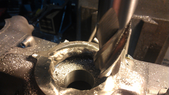
From here the order isn't that vital but I chose to "face off" the excess weld material from ouside the crankcase. This is easily done in the mill (or a large drill press, I suppose), and you can see that process in action in the image at right.
After machining it off, I finished the job with a hand-file
Now, while the case is on the mill table, center the quill in the crankshaft bore as perfectly as you can and then a clearance bore needs to be cut into the crankcase. This is to permit the boring bar's cutter to receed into the case as you bore the new pulley bore. (see this happening below)
 The
bore for the pulley is nearly the same as the bore for bearing 4, so a standard
boring bar cutter for bearing 4 can be used, but the cutter's fixture is very
large relative to the bore to be cut, so before the cutter could be fitted,
a pre-boring has to be performed - just to get the cutter inside the crankcase.
No problem!
The
bore for the pulley is nearly the same as the bore for bearing 4, so a standard
boring bar cutter for bearing 4 can be used, but the cutter's fixture is very
large relative to the bore to be cut, so before the cutter could be fitted,
a pre-boring has to be performed - just to get the cutter inside the crankcase.
No problem!
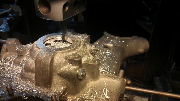
We (previously) installed the adapter into the case, so center the quill on the center of the special adapter, and make a preliminary bore using a standard boring head. And, here you can see that operation happening.
It is important to point out that while you may be tempted to simply bore to size here, this way, it's a mistake to do so because you simply cannot get it true to the crankshaft bore this way! In other words, it's not just centering up, but the pulley bore needs to be concentric with the crankshaft bore, so it must be bored the same way main bearing bores are cut - using a boring bar that centers on the crankshaft bore itself, on both ends of the crankcase (flywheel end and bearing 4).
 Now,
bore to size
Now,
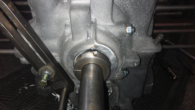
bore to sizeSo, its time to mount up the boring bar with the cutter set to the diameter of a new crankcase's pulley bore.
In the image at right (which was taken after the operation), if you look carefully, you can see the special "boring bar support bearing" made earlier just beyond the cutter.
You can also see why the preliminary boring was necessary - the cutter's holding fixture that mounts to the bar is large and barely fits!
I should point out that there's a subtle optical illusion here - at least when I look at this image; the cutter only sticks up a tiny bit from its holder whereas here it looks positively gigantic! I think it's just the angle of the shot accentuates the appearance of length.
To help with this visual, I dug up another image from when I had done this on another occasion. In this next image, also taken after the boring operation, the boring bar has been withdrawn such that the cutter lines up almost perfectly with the outer edge of the pulley bore. The gap we can see is because the camera is just a little "high", so we're peering down behond the cutter.
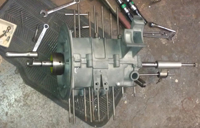
Oh, and for those less familliar with performing an align bore and who wish to know about the apparatus, the image below shows this boring procedure being performed, but it's the identical process to when all the crankshaft bearing bores are cut.
That's a hand-crank on the left, sticking nearly vertical. On the flywheel end of the crankcase, there's a large iron (possibly steel) fixture that supports the boring bar at that end. It centers on the flywheel seal's bore. The pulley end is usually supported by a similar part installed into the pulley bore, but in this instance it's supported by our special bushing we made as outlined above. The gadget on right, with the thumb screw way out at the extreme right end, is a special device that moves the cutter along the bored axis very slowly so that an ultra-fine boring finish is achieved.
The last step is to "back cut" the groove where the oil slinger goes. (The oil slinger mounts to the crankshaft.) This step removes the excess weld material from the area where the slinger goes. For this I use either a pneumatic "die grinder" with a tapered bit, or a fiberglass cutoff disc. Either work well.
There, you're done!
When you're ready for work on your machine, just let us know.