Copyright © 2007 - 2025, Coachworks For contact data Click Here.
Copyright © 2007 - 2025
Copyright © 2007 - 2025,
Coachworks For contact data
Click Here.
![]()
We've had to do all sorts of crankcase repairs over the decades, and one thing we just had to do again - to make a new size - was make supports for our boring bar that fit existing main bearing saddles.
The fundamental reason to do this is because it's vital all crankshaft saddle bores (and, for two-piece-case engines, the pulley bore, too) be in perfect alignment - "concentricity"! (Rubber oil seals are a lot more forgiving about perfect alignment.)
![]()
WHY you may have to do this can have many causes, and we've had to do this quite a few times for several different reasons. If you can't do this, often the result is a scrapped crankcase, or it's life shortened because of a lack of such ability, knowledge, or skill. We've even saved quite a few old two-piece cases that were set aside for such lack - and fixing a pulley bore requires the ability to weld magnesium, too!
What this process provides is the ability to cut (or reface) a bore that is concentric with existing bores. This is, after all, what your normal boring bar technology does. The innovation here is just applying that to extant bores in your case
 So,
we make them for our own use. And, since we just had to do this again, we figured
we'd take photos and share how with the wider community - this is no real secret
to a competent shop, but so few are either competent today or willing to take
the time to do it...
So,
we make them for our own use. And, since we just had to do this again, we figured
we'd take photos and share how with the wider community - this is no real secret
to a competent shop, but so few are either competent today or willing to take
the time to do it...
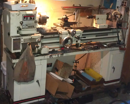
AT RIGHT: A vital machine tool - here's the one we used - a lathe.
As noted above, this can be done for fixing a pully bore, and if that's what you're doing, you'll also want to see this other page where we discuss doing this specifically for a crankshaft pulley bore. But if doing that, it might be worth reviewing this material, too.
For the curious, this time we did it to help preserve the life this 1962 1600S during its rebuild (jump here to get right to the trouble spot).
The outside diameter must be at least a snug "net-fit," but we like a one thousandth interference fit (0.001") as these are too thick to "crush" like a normal crankshaft bearing.
 As
noted above, this work does not have to start with round stock as seen below.
As
noted above, this work does not have to start with round stock as seen below.
If you have a precision bore gauge, use that and we recommend about one thousandth inch (0.001").
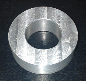
AT RIGHT: This one fits a nose bearing (bearing 4) and was made from a thick sheet of AL stock, not round bar, as covered below.
Short of that, if all you have are micrometers, use the specifications book or other reference to get the right basic data for your engine - that is, what size are you even trying for? If going from a book, check both the case bore and bearing OD for a sanity check. Most have a 0.05 mm (0.002") crush, or interference fit. However, these won't crush like a crankshaft bearing does, so we recommend less, so long as it isn't lose in the case! As noted above, we recommend 0.001".
The inside diameter must match the requirements of your boring bar. We use a Port-A-Tool brand boring bar and it uses a nominally one inch bar. The fit needs to be as good as you can get it. We shoot for ONE thousandth of an inch clearance, but two isn't bad.
This is straight-up machine work. There are several ways to do this, but as an alternative to the round stock shown below, in the past we've started with a thick plate of aluminum, cut out a chunk big enough on a band saw, then drilled an M8 through-hole with a 1/2" step. This bore and step are so to fit it onto a special holder we made that lets us mount it in the lathe easily.
While the fit has to be good, always remember that if you blow it, you can always start over with a new chunk of stock!
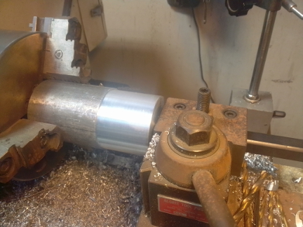
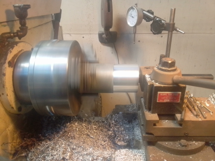
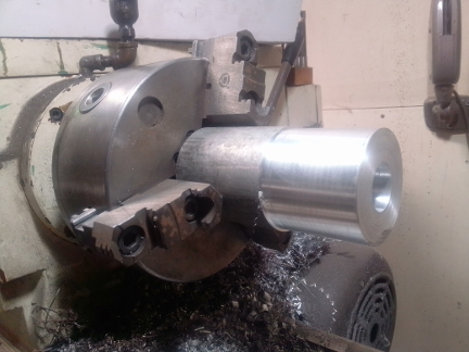
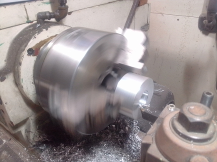
BELOW LEFT & RIGHT: What's happening should be obvious, but we missed taking some images between them, namely boring an initial bore through (deep enough in) the stock. The process was to simply start by using a small drill to center using the lathe to turn the part and a chuck in the tail stock to hold a bit. And then we stepped it up once to get a strong bit in there to go deep enough without any risk of breaking off the bit, and then a 3/4" bit to get us a bore large enough for our boring bar - the tail of which is seen in the image at right.
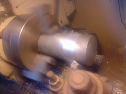
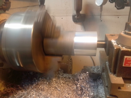
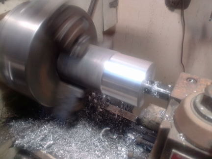
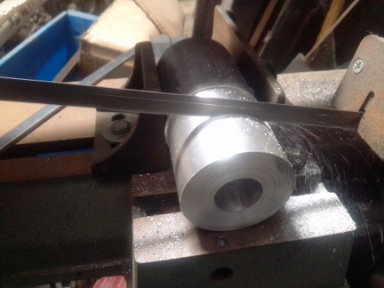
ABOVE RIGHT: In this last image of the above series, the process of chamfering the outside and inside corners is being performed. This is highly desireable for many reasons...
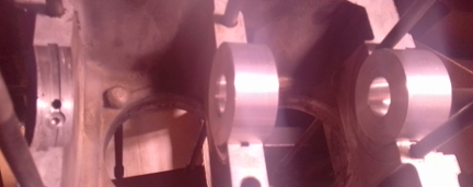
AT RIGHT: Here installed, awaiting first use.
Note that they appear extra-wide. The one at bearing 2 (center of image) isn't extra wide but looks it because it's thick enough to serve in any bearing position and #1 is wider. The one at bearing 1 ("flywheel", right edge of image) is wider because of an issue with the ID: It turned out that the carbide cutter we were using to cut the ID had a chunk of AL stick to it as we finished the cut, so we just went deeper while we had the chance! We just didn't bother to cut off the excess length.
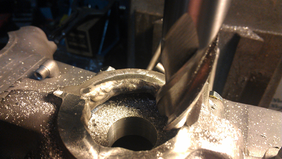
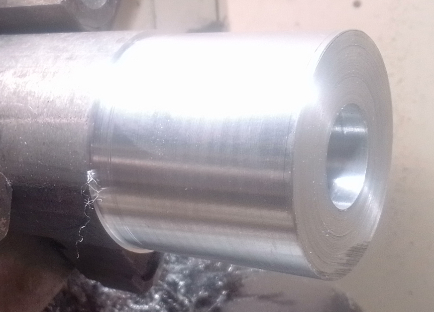
BELOW: Here you can actually SEE the issue with the bore change: Note the color change inside the bore! That's where, as the cutter was withdrawing for the last time, it got a burr - a chuck of AL - stuck to the cutting tip, thus making the bore larger! Oops! As noted above, our solution was simply to use the length to not have to re-do it. BE CAREFUL! Check your work! We always do!
We thought this image might be helpful, showing a # 4 bearing boring bar support installed as a part of saving this very early Porsche crankcase. Note it installed already in this image.
For the full story on that, see this page.
When you're ready for work on your machine, just let us know.