Copyright © 2007 - 2025, Coachworks For contact data Click Here.
Copyright © 2007 - 2025
Copyright © 2007 - 2025,
Coachworks For contact data
Click Here.
![]() has been retained for reference purposes.
has been retained for reference purposes.
 This
engine was completely rebuilt as outlined on this page, sold as a long-block,
and then run-in on our Stuska water brake engine dynamometer to Porsche's specifications
using borrowed completion parts.
This
engine was completely rebuilt as outlined on this page, sold as a long-block,
and then run-in on our Stuska water brake engine dynamometer to Porsche's specifications
using borrowed completion parts.
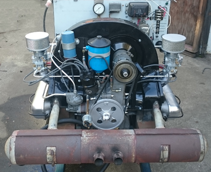
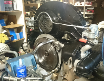
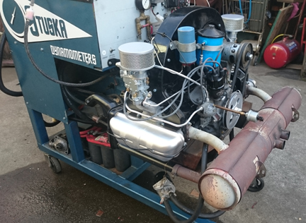
AT RIGHT: The engine mounted to the dyno prior to running-in. There's a detailed description of the running-in of this engine way down near the bottom of this page.
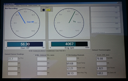
BELOW: Following run-in, this image shows the dynamometer's display screen showing corrected horsepower developed - a bit over 56 bhp at about 4100 RPM, which is a tiny bit more than the official stock specification (55 bhp at 4400).
 ...YES,
the muffler is the wrong one, and so is the fan shroud and several of the other
parts. These parts were just "borrowed" for the run-in process,
along with virtually all the rest of the accessories, as outlined below.
...YES,
the muffler is the wrong one, and so is the fan shroud and several of the other
parts. These parts were just "borrowed" for the run-in process,
along with virtually all the rest of the accessories, as outlined below.
Note that the run-in process is performed on our Stuska Water Brake Dynamomenter, as per Porsche factory specifications as outlined in the Workshop Manual, "Running-In and Testing" operations, 43 EN and 44 EN, pages E51 and E52.
 While
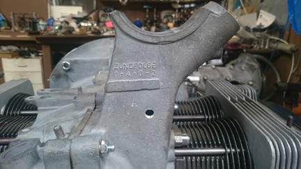
this case has "no numbers," the case casting dates are in 1953.
While
this case has "no numbers," the case casting dates are in 1953.
PLEASE NOTE
The photos here may seem like they're from two different engines - this is because
this engine was completely re-assembed TWICE! The engine was put
up for sale, bought, and the buyer figured it was too grey and he wanted the
crankcase "plated" in a particular manner, even though it was already
plated using the Dow 19 process, and even though we cautioned against. He supplied
the "Alodine". We followed the procedure as directed and it streaked
badly, probably due to some chemical incompatibility. To resolve this, the engine
was disassembled, the case was media-blasted clean, washed with acetone to
remove any finger oils from handling then plated his way, again. In our
opinion, it looked better before, but we do whatever it is our customers are
willing to pay us to do - so long as it's legal!
We have also added materials pertaining to the running-in of this engine and other post-sale details, as it may be of interest to the buyer or others.
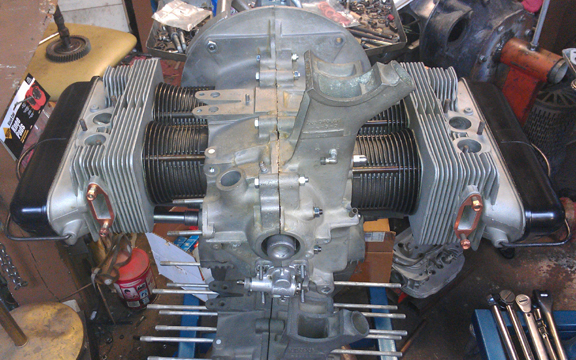
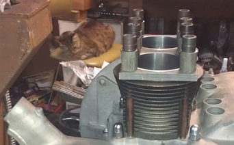
ABOVE RIGHT: This engine after the first assembly. The case is plated with the Dow 19 process. Note also that the valve covers shown here are not the correct ones, which were out being plated at the time.
Given the note above about two assemblies, some of the photos - and descriptive text - are from the first assembly, and some from the second, but it's the same parts being installed in either instance.
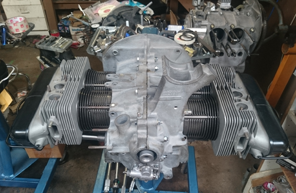
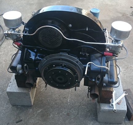
BELOW RIGHT: This engine after the second assembly, with the case plated with the "Alodine" process.
This 1953 356 1500cc engine is completely stock and correct, and has just undergone a complete overhaul, and is fully balanced for smooth running, long life, and a few more HP. The purpose of this page is to document the steps used in assembling this engine
The crankcase is "numbers matching" and is in very good condition. The expression "numbers matching," when it comes to two piece crankcases, simply means they were manufactured together as a pair and remain so.
The crankshaft has been upgraded to the "B" series, which are less prone to cracking. It is fitted with new, original-size pistons and cylinders.
 Every
detail about the engine has been attended to, as outlined below; nothing
was overlooked. If something isn't clear or has for some reason not been documented,
please contact us.
Every
detail about the engine has been attended to, as outlined below; nothing
was overlooked. If something isn't clear or has for some reason not been documented,
please contact us.
In the interests of both brevity and accuracy, I / we have been interested in these engines since the late 1970s and have been collecting parts. ...After a while, some of the bits get confused with one another. So, we really haven't got anything useful about the older history. However, I got it decades ago, and kept it on my engine shelf where it has sat until recently. The earlier history is completely unknown, but many people have seen this engine sitting on the engine shelf in my workshop, so you could perhaps jokingly call it a "well known engine!" (I have several like that!)
Unfortunately, it didn't occurr to anyone to photograph the teardown process.
The first thing to do was prepare the crankcase. OH what a CHORE!
I should have cleaned it up YEARS before, back when we could get real solvents. The parts washers of today just plain don't work in comparison to the old stuff. DAYS were spent soaking! MORE than 12 hours were spent scrubbing with a modern "hot" water-based "solvent" parts washer, just trying to get the crankcase clean! Eventually I got it clean enough to media-blast and then removed and replaced all the "soft plugs" that plug the various oil drillings - this was done to ensure that ALL the oil passages are perfectly clean!
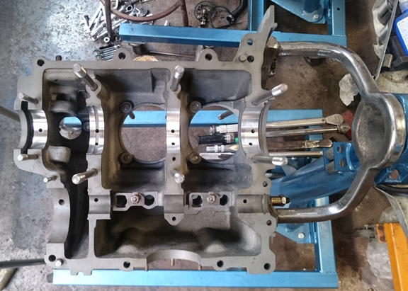 Unfortunately,
I didn't think to take any "before" photos showing what the case looked
like prior to cleaning - if I'd had any clue that it would be this difficult,
I would have because it would be very enlightening to see just how long it takes
to clean up a mess! If it weren't a rare, two-piece crankcase, I don't think
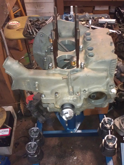
I'd have bothered! However, the image at right shows the hardest area to clean
- the casting parting-line that runs horizontally in the sump area just visible
below the camshaft support area. Note how clean the sump is now!
Unfortunately,
I didn't think to take any "before" photos showing what the case looked
like prior to cleaning - if I'd had any clue that it would be this difficult,
I would have because it would be very enlightening to see just how long it takes
to clean up a mess! If it weren't a rare, two-piece crankcase, I don't think
I'd have bothered! However, the image at right shows the hardest area to clean
- the casting parting-line that runs horizontally in the sump area just visible
below the camshaft support area. Note how clean the sump is now!
Following this, as discussed earlier, I replated the crankcase, as was originally done, with the Dow 19 process. This process sometimes creates a brownish gold coloration, but in this instance, it just made the crankcase a more consistent grey. The real benefit is that it helps protect the magnesium, which is very galvanically active.
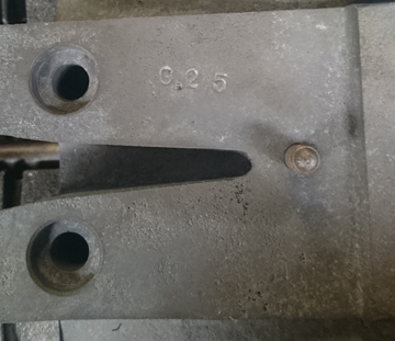
The case was then "align-bored". This is the process of slightly enlarging the crankshaft main bearing bores to accept a larger size main bearing. In this instance, the bore was still "standard" - 60mm - however, it had some wear and was not runnable at that size. So, it was bored to 60.25mm, which is the stock standard size for the younger three-piece crankcase engines. ...Sometimes an over-boring of more than one "step" is required, but in this instance, the case cleaned up beautifully as can be seen in this image.
At this point, the crankcase underwent a "final check." Thankfully, the oil pickup tube is very tight in the case. (It can be challenging to repair a loose pickup tube.) And, all the threads are fine, including the rear-most two, that accept the forward pulley shroud. These are often stripped. Because the outermost thread or two are often not very sturdy due to the use of too-short fasteners and too much torque, I ran a tap through and cut a few more threads just to ensure there's no problem later. (Long M6 bolts should be used here - which is good advice anyway.) And, unusually, all of the sump studs are in great condition!
Not forgotten, the cylinder "decks" were checked that they are in one plane with their immediate neighbor using a special tool designed just for this purpose. And, there's a reason for thorough checks like this; in this instance, both halves had a low-spot of between three and four thousandths of an inch in the area where the two cylinder spigots come close together - a common situation for these older magnesium cases. That is, the cylinders would be slightly canted toward each other if nothing were done about it - and, of course, the cylinder head to cylinder seal would be stressed and could leak. The specification is 0.1mm, or, about 4 thousandths - too close for my tastes as it's basically at the official limit. I could have just gone with it, but decided instead to "deck" the cylinder spigots, so the case is ready for long life.
With the poor lighting at the mill, the photos I took of the process didn't
turn out, but in later images, look for the bright rings around the cylinder
spigots!
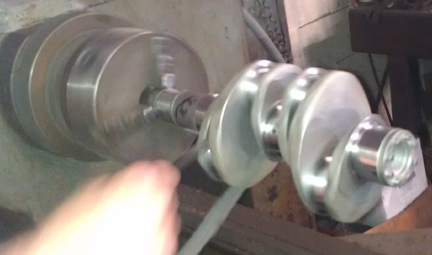 As
cited above in the background section, no crankshaft or rods yet remained with
the case. It happens that the early "pre-A" (and even A) crankshafts
are more prone to breaking than the younger cranks are. So, I selected a "B"
series crankshaft for this engine because of the cracking problem with the older
ones. It was reground to second under on both rods and mains (nominally 49.5mm,
and 52.5, respectively) which means, all other things being equal, it's about
exactly half way through its total service life.
As
cited above in the background section, no crankshaft or rods yet remained with
the case. It happens that the early "pre-A" (and even A) crankshafts
are more prone to breaking than the younger cranks are. So, I selected a "B"
series crankshaft for this engine because of the cracking problem with the older
ones. It was reground to second under on both rods and mains (nominally 49.5mm,
and 52.5, respectively) which means, all other things being equal, it's about
exactly half way through its total service life.
AT RIGHT: The crankshaft being polished.
Just to be sure, I had it magnifluxed to check for cracks and then thoroughly cleaned and polished it.
I then pulled out a set of already rebuilt rods, mounted the crank in the crankshaft stand and installed the rods.
For me, "rebuilding the rods" means to:
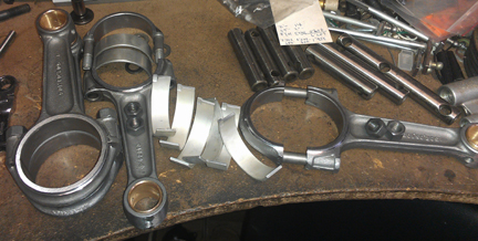 Clean
and inspect the rods - reject any that have been through trauma
Clean
and inspect the rods - reject any that have been through traumaAT RIGHT: The rods having their bearing shells installed. Note how the tangs on the bearings are, when the tang end is up, on the left side. These are known as left hand tang rod bearings and are the mirror image of the younger type. Left hand tang bearings are no longer available - these came from my stash.
This is all standard work so there aren't any photos of them in-process. However, here they are when assembled onto the crankshaft:
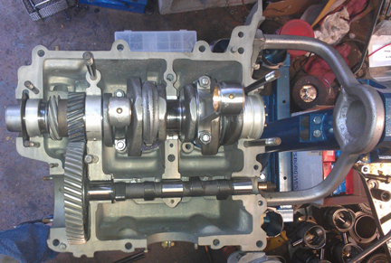
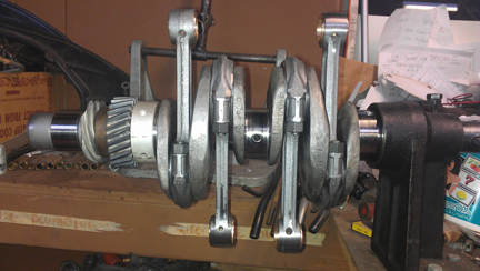 AT
RIGHT: Here the crankshaft is fully assembled with the third main bearing,
cam and distributor drive gears, and all the rods. Note how the small ends of
some of the rods look polished - that's from the balancing process.
AT
RIGHT: Here the crankshaft is fully assembled with the third main bearing,
cam and distributor drive gears, and all the rods. Note how the small ends of
some of the rods look polished - that's from the balancing process.
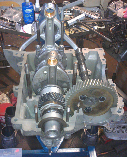
Back in the early 1990s I got a large stash (about two dozen) of new camshafts for two-piece crankcase engines from Ritchie Lukes. So, I dug one out for this engine. This particular one had been ground by his friend Dema to be a little bit hotter than stock, but not as hot as used in the Super engines. I think a new camshaft is a nice touch! ...I didn't think to take any images of it by itself, but there are images of it laid in the crankcase awaiting assembly, so, I'll run those images here. There are images of it later on with the gear mounted.
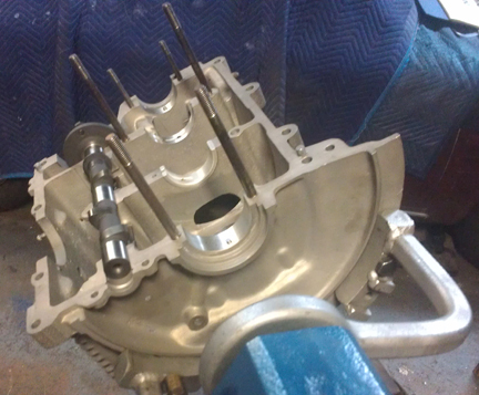
ABOVE LEFT AND RIGHT: The crankcase is now ready for assembly with the dowel pins and middle main bearing installed. The camshaft has been laid in place but the gear hasn't been installed yet. Note the coloration differences in these images - the difference is primarily the effect of lighting, however the one on the left is from the first assembly (Dow 19 process) and the one on right is from the second ("Alodine").
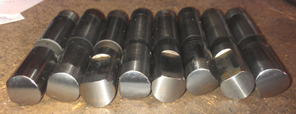
As you can see the lifters were refaced and are wonderful! The photography was rather difficult, though, because the parts are so shiny, it's hard to get an image that shows the face of the metal properly. One aspect of trying to get good images that I think is interesting is how with some of these images, my efforts to get a good clear image has resulted in magnification, so the images here are larger than the actual parts!
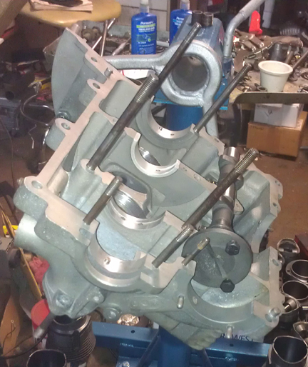
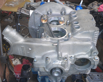
Crankcase preparation, described above, was a real chore. But assembly was a breeze! In the camshaft section above, the main bearings and cam were trial-fit. Here, the left half is completely ready for assembly.
ABOVE LEFT AND RIGHT: here the crankcase is ready for the opposing half to be installed. All items are assembled into the left side, as usual.
Within a few minutes, we move from what we see above to a short-block, seen here:
Note the new cap nuts used to secure the case halves together!
Shortly thereafter, the oil control piston, spring, and retaining cap were installed. Then, the head studs, and move on to cylinders...
 Time
to install the Pistons and Cylinders.
Time
to install the Pistons and Cylinders.
At this point, I had a decision to make as I had the following options:
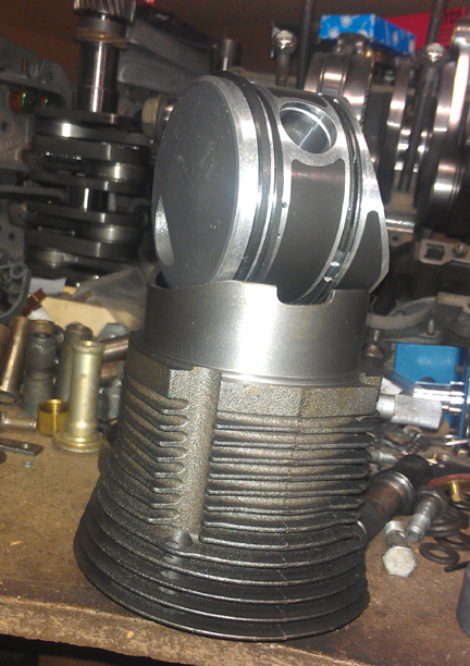
After talking with a number of people, I settled on the new set - one piston and cylinder pair is imaged at right. (However, if you prefer an alternative choice, I can accommodate that for you - the heads can always be taken off and a different set fitted, so lets talk about that if that's what you want.)
AT RIGHT: The piston and cylinder pair at right are the new modern reproduction. I've used them in close to a dozen engines so far without any problems.
In my view, while the stock specification for weight-differential in the pistons of early engines is something like 16 grams, if I recall correctly, piston weights need to match very closely in any single set, and I strive for 0.1 gram. This set was out by only about one and a half grams - not too bad for a standard production tolerance for a cast set. (Many high-performance builders say within one gram is fine - but the closer the better.)
New parts are not exempt from careful checking!
We always check the match pistons to cylinders and match piston weights as a set, and provide any remedial action to correct any errors before installation. For example, by shuffling around the piston pins among the pistons, one can usually improve the matching of piston weights. This set naturally balanced (without removing material) to within 0.2 grams.
For many shops, from this point, installation goes very quickly, but we think this is where one needs to take one's time! The key reason one needs to take time here is that there are production tolerances on every part in an engine, and while a set of parts may look identical, there's often subtle variation between members of a set, and there are sometimes significant errors in production that weren't caught by the manufacturer's quality control processes. These errors can "stack up" and cause problems if not discovered and corrected.
 Here's
our process: Two of these steps require special tools most shops don't
have.
Here's
our process: Two of these steps require special tools most shops don't
have.
We like to carefully measure everything and then mix-and-match the parts for superior fit. We have also discovered significant manufacturing errors with this process which would likely have gone unnoticed without these measures. It is remarkably easy, for example, to overlook the circumstance of the crankshaft bore not in the true center of the crankcase, angled on the horizontal left or right of center, or not on the same horizontal plane at all. Yet examples of errors like these are not as uncommon as we would like.
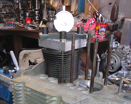
The height comparison check (visible above right) is done to ensure that there are no differences between the cylinder heights that the head itself "sees." The book value for tolerated error is 0.1mm (four thousandths of an inch), but in this case, there was no measurable difference between either pair, which is not all that surprising given that the case was both align-bored and decked. However, it's especially important to check.
By the way, it's hard to see in the image above right that the cylinders are in fact not touched on the surface that seals with the cylinder head. That may be better seen in this next image, at right: The cylinder's head sealing surface protrudes through and is not touched by the clamping tools.
 The
next thing we do is something nobody else does (that we know of) in the
engine building process, and that is to measure the height the piston crown
comes above the plane of the top of the cylinder. I call this the CAC,
or "Crown Above Cylinder." This value is important because, firstly,
it can reveal deeper problems, and because it helps us get the compression ratio
equal in all four cylinders.
The
next thing we do is something nobody else does (that we know of) in the
engine building process, and that is to measure the height the piston crown
comes above the plane of the top of the cylinder. I call this the CAC,
or "Crown Above Cylinder." This value is important because, firstly,
it can reveal deeper problems, and because it helps us get the compression ratio
equal in all four cylinders.
Here are some of the deeper problems that can be discovered through a CAC check:
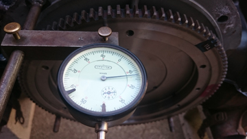
In order to do this for these engines, you have to have special tools. Here, you can see them in action in the image at right.
Even if you can't read the needle in this image, the distance between the smallest tick marks is one hundredth of a mm, or 0.0004" - LESS than half a thousandth of an inch - and you can discern to perhaps a tenth of that! So, this is a very accurate measure, performed while the cylinder is under torque, so any shims are squished flat, etc.
The accuracy is so good, that if you take the time to swap parts around, you can accurately determine discrepancies in the manufacture of the various parts even if you can't measure the parts accurately enough individually! But, we ARE splitting hairs here! However, a benefit to both engine builder and customer is that the ability to move parts around for better fit means that perfection is more easily achieved, and the more equal the HP production of each cylinder, the smoother the engine will run, the more HP the engine will produce overall, and the longer the engine will last in service.
Because this process includes the entire assembly, torqued as in service, and measures the height each piston protrudes out of its cylinder, all errors in connecting rod lengths, cylinder heights, crankcase spigots depths (cylinder bore deck), piston connecting pin heights, and shim thickness' are accounted for in the measurement results. There is no superior method.
Eventually, all the cylinders have been trial fit and measured, etc, and you're left like this, ready to know what the combustion chamber volumes are inside the cylinder heads so you can shim the cylinder bases as appropriate to match the compression ratio right-to-left.
 Cylinder
Heads
Cylinder
HeadsThese heads are in great condition - I found no cracks or broken fins - but it does not appear they were actually originally paired together. The guides were of the 10mm variety, but they still had bronze seats in them. (Bronze seals well but wears out quickly. Also, bronze can't take the unleaded fuels we have today.)
The heads were washed with the aqueous parts washer, then media blasted clean. Then the machine work was performed, the seats ground, they were washed again, blown clean with compressed air, and then carefully assembled.
New seats were installed all around. And, while at it, all new guides were installed, too. That's very easily said, but very hard to do correctly! The reason is that the specifications book lists three different setups, and none of the parts are readily available anyway. So, you have to carefully measure what system is presently installed - and this many years on, and with clear evidence that someone had been working on these heads and did not do a complete job, you cannot trust that all the guides or seats are of the same type! The valve guides and seats had to be made for these purposes "from scratch." (Pretty useful stuff, that scratch!)
I didn't think to take any photos before working on them, so the photos begin with the guides and seats already installed.
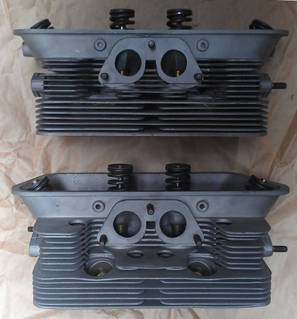
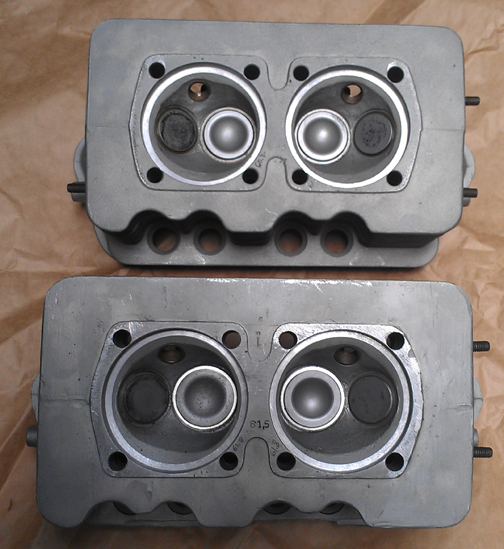 In
the image at right showing the combustion chambers, you can see everything is
installed. If you look carefully you can see the different combustion chamber
volumes written in ink; the book says they shall not be more than 1 ml different.
Remarkably, the lower head has both chambers exactly the same volume! The upper
head is 1ml smaller than the other head, and the fourth chamber is just a little
bigger. Note that the factory assumed you would shim all four cylinders the
same, but today we regularly shim left and right sides of an engine differently
so we don't have to take metal out when it isn't otherwise necessary! So, the
upper head got extra shims under the cylinder bases than the side that got the
lower head.
In
the image at right showing the combustion chambers, you can see everything is
installed. If you look carefully you can see the different combustion chamber
volumes written in ink; the book says they shall not be more than 1 ml different.
Remarkably, the lower head has both chambers exactly the same volume! The upper
head is 1ml smaller than the other head, and the fourth chamber is just a little
bigger. Note that the factory assumed you would shim all four cylinders the
same, but today we regularly shim left and right sides of an engine differently
so we don't have to take metal out when it isn't otherwise necessary! So, the
upper head got extra shims under the cylinder bases than the side that got the
lower head.
Visible here, the heads were both fly-cut because to install seats, the heads have to be heated pretty high, but cannot be supported during that period and they can warp slightly. Decking ensures the cylinder sealing surfaces are in the same plane. Then, usually, the surface closest the crankcase gets cut down to match however much was taken out in cleaning up the cylinder sealing surface, thus ensuring the heads don't foul on the cylinder's top fin. However, in this instance there was plenty of clearance, so that step was skipped.
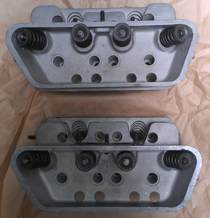 The
valves were all cleaned, refaced and polished. And of course, the valve seats
were ground (after the above photos were taken).
The
valves were all cleaned, refaced and polished. And of course, the valve seats
were ground (after the above photos were taken).
It was decided to use single springs instead of the original dual-springs, as provided for by Porsche - the so-called "third version". Someone said as recently as December 17, 2012, that RIMCO did their two piece case heads recently, so I called them to see if they had any more two-piece-case valve springs. They said they did! However, when I started prattling off dimensions, the fellow stopped me and said that no, based on the measurements I gave him, these are NOT the correct springs! (Just as I suspected. By the way, the correct dimension data is in the little specifications book, version three.) BE CAREFUL what you buy! Lots of people think Two Piece Case valve springs are the same as the younger engines, but they are not!
Of course, not just the spring, but the installation is vital. Just as with other engines I build, the springs are shimmed where the valve and retainer are position specific, and where the strongest springs (there is always some variation) get the heavier (intake) valves. This is done so that all the valves float at the same time and thereby give a good signal to the driver to back off!
Now, we mount the heads and finish off the long block. We first use our data on combustion chamber volumes and CAC (Crown Above Cylinder) data and calculate out which side each head should go on and what shimming should be used to end up with what compression ratio.
 Final
Assembly
Final
AssemblyAT RIGHT: This engine after the second assembly - "Alodine" process plating.
OK, time now to do a little more on the crankcase...
Oil pump, sump screen and cover, oil control piston - only took a few minutes.
Here it is as a longblock, minutes away from being ready for pickup or delivery!
Yes, the distributor drive shaft has not been installed because it should be left out until a distributor will be installed. Otherwise, if anyone rotates the engine backwards, the drive gear will ride up on the bronze crankshaft gear and may damage it....
Oh, and let's not forget to mark that the case was align-bored to an unusual size! (This size is standard for the 3 piece crankcase engines, but Porsche & VW only provided a half-mm oversize for these cases. So, this is "unusual.")
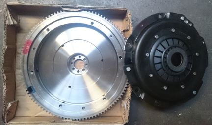
For a flywheel, I went with one of the new reproductions that's available with a 6v ring gear and 200 mm clutch surface. On early engines like this one, 180mm was standard and the 200 was only used on racing engines originally, with a very rare and expensive Hauserman diaphragm clutch plate, but back in the day, asbestos friction disks were standard equipment. Today, the modern asbestos-free clutches don't really work as well and if the engine has a good day, the 180mm clutch may slip, so going with a 200 is good advice. I mated to this a modern production diaphragm clutch. It will work as-is perfectly well with any transaxle up until (that is, prior to) the T-6 B series which uses a guide-tube for the throw out bearing, and, the T/O bearing friction face can be removed from this clutch for use with transaxles that have a guide tube. So, you're good to go.
BELOW LEFT AND RIGHT: A new 200mm flywheel was chosen, with 6v ring gear and VW depth clutch, mated to a new, heavy-duty diaphram type clutch. These are balanced together (see the lightening drillings, upper right parimeter of the pressure plate), and then attached via a brand new gland-nut, pictured left.
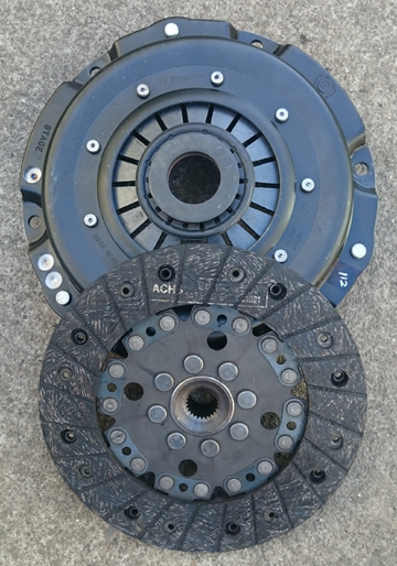
AT RIGHT: Once again, the pressure plate, but this time with its friction disk, a "fixed type" Sachs brand (OEM).
Because the engine was on the stand at the time, mounting of the flywheel, setting of the end-play and installation of the clutch were delayed until the engine was dismounted - it's a little easier when not up on the stand.
 Epilogue
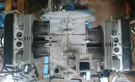
As stated way up at the top, this engine was sold as a long-block to someone who had us tear it down, re-re-plate it with "alodine" (which accounts for the different shades of crankcase seen in these images), and then the re-reassemble it, of course. Here in the Epilogue section, you see the second incarnation of the long-block being assembled into a running-engine.
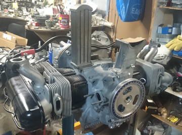
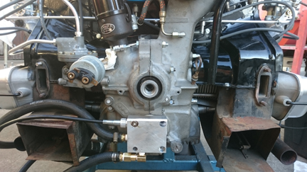
AT RIGHT: The long-block starts receiving "accessories", such as manifolds and oil cooler.
There was a shortage of "completion parts" - sometimes called "accessories" - but they wanted us to run-in this engine on our dynamometer. We got some of the completion parts for them, and the rest we supplied as temporary loaners for the run-in process. We chose period-pieces wherever we had the suitable item, but used later parts in some instances.
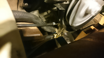
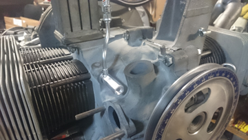 AT
LEFT: An original oil-line banjo bolt is a rare item today...
AT
LEFT: An original oil-line banjo bolt is a rare item today...
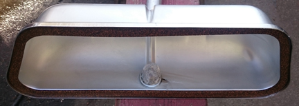
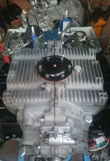 AT
RIGHT: A good view of the now completed sump. Note the new rivet in the
sump plate. The plate was powder-coated and the magnet re-riveted on. And, the
rest of the hardware was plated, too.
AT
RIGHT: A good view of the now completed sump. Note the new rivet in the
sump plate. The plate was powder-coated and the magnet re-riveted on. And, the
rest of the hardware was plated, too.
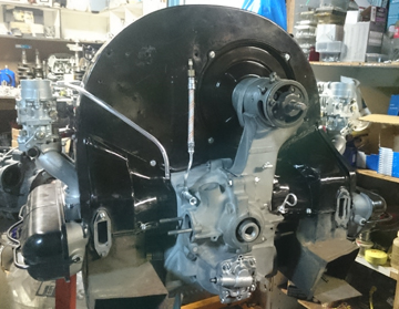 AT
LEFT AND BELOW LEFT: Almost ready to come off the engine stand. However,
before it was removed from the stand, the distributor shaft was installed, then
the fuel pump, then the distributor, followed by plug-wires. Unfortunately,
no further images were taken while it remained on the stand.
AT
LEFT AND BELOW LEFT: Almost ready to come off the engine stand. However,
before it was removed from the stand, the distributor shaft was installed, then
the fuel pump, then the distributor, followed by plug-wires. Unfortunately,
no further images were taken while it remained on the stand.
The next focus - after removing it from the engine stand - was on setting the end-play so that the flywheel could be permanently mounted, followed by the clutch assembly, as the next major step was to mount the engine to the dynamometer.
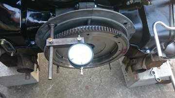
BELOW RIGHT AND LEFT: The flywheel end play is set to just about the theoretical perfect 0.125mm as can be seen here. (The range is 0.1 to 0.14mm with a wear limit of 0.2.)
AT RIGHT: Ready to mount to the dynamometer which will serve as a stand while the exhaust system is mounted. If you look closely, you can see in this image that the clutch "cover" is retained by the correct 10.9 grade socket-head screws instead of hex-head bolts.
Oops! Almost forgot the correct valve covers! Here's the inside of one of them - note the screen is NOT all smushed up - the other one is almost as good:
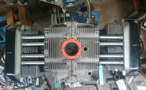
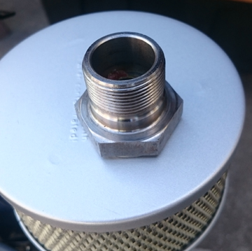
BELOW RIGHT AND LEFT: The buyer also opted for our new full-flow filter system which does NOT require modification of the crankcase. Here it is, installed and hooked-up to both the full-flow filtration AND a mechanical tachometer! In the image at right, the pully shroud is mounted to ensure clearance, and the engine is at that point running!
BELOW RIGHT AND LEFT: The engine on the dynamometer, after mounting the exhaust system but before attaching the various wiring required for running on the dyno. The muffler is from a "C" series. The crankshaft pull is "the large OT pulley," correct for the 2 piece case era, but the generator and generator pulley are from a younger engine and, notably, we tried a 3 piece case style generator pulley but had no belt that would work with it, so it was swapped for a 36hp VW unit for the run-in process because it, combined with the OT pulley, only requires a standard "6v VW" fan belt which was on hand. Note also an oil pressure sending unit has been mounted which passes to the left of the crankshaft pully and above the muffler.
 As
for "running-in", as described above, this is done on our
Stuska Water Brake Dynamomenter, as per Porsche factory specifications as
outlined in the Workshop Manual, "Running-In and Testing" operations,
43 EN and 44 EN, pages E51 and E52.
As
for "running-in", as described above, this is done on our
Stuska Water Brake Dynamomenter, as per Porsche factory specifications as
outlined in the Workshop Manual, "Running-In and Testing" operations,
43 EN and 44 EN, pages E51 and E52.
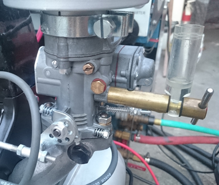
AT RIGHT: Checking the height of the fuel in the float bowl. The sight-glass is universal to all Solex carburetors (that we know of) as it threads in where the main jet carrier normally goes. Here it is installed in the right-hand, recently rebuilt PBIC carburetor.
After the running-in, we finally got the rebuilt carbs in-hand and, while the engine was still on the dyno, installed them. The float-height was then checked, injection quantity set, butter-flys set, idle mixture and then checked for overall running, finished off with an exhaust gas analysis to confirm settings.
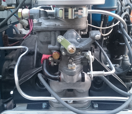
AT LEFT: The left-hand PBIC is fitted with a "starter", which is the part of the assembly with a lever pointing to about "10 oclock".
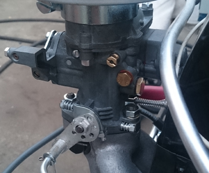
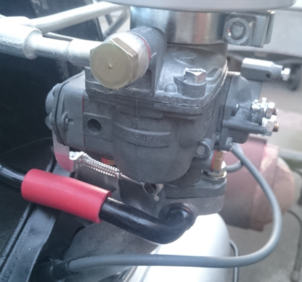
ABOVE LEFT AND RIGHT: The left-hand carburetor is shown. In the left image, it can be seen that the sight-glass used for checking float height cannot be fitted to this side when the carburetor is installed on an engine. However, because the two carburetors are identical in most respects, with identical floats and related parts, any adjustment needed by the one is also needed by the other. Note also that Porsche normally only fitted the starter to the left hand carburetor, in part because two aren't normally necessary, and also because of clearance issues with the fan shroud on the opposite side, like the sight-glass. ...Additionally, here can be seen, in the right image, the manifold connection. The red tubing is normally retained with small key straps, just like are used on solid axle boots, only smaller. Here, they were left off because this is not the final assembly of this engine and the tubing was sealing well without them - they are being provided (new, of course) to the buyer.
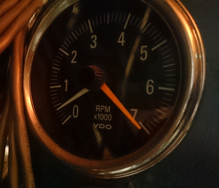
It turned out that the carbs wouldn't idle below 1000 RPM. That's an OK idle, but it masks problems. The book specification calls for an idle between 600 to 800 RPM, and, frankly, achieving a stable idle below that is near unto impossible! However, this set (imaged above) just wouldn't go that low and that means there's something wrong.
We originally hired out the rebuild of the carbs just due to time - and, we figured someone who specializes in Porsche carburetors must do a great job. So, with our carbs NOT working properly and with our customer coming soon (we thought), we had a decision to make: suffer even MORE time shipping back and forth (and who knows if they'd come back any better or in time?) or diagnose them (and in the process, lose the ability to get compensation from the shop that rebuilt them) or we could do what we did: build another pair. ...They look identical, of course, so, no new photos needed, however we took a photo of the engine idling at 400 rpm - which basically proves that everything is perfect! This was a stable idle...
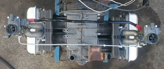
Following proving that these carburetors are high-quality, tuned for THIS engine and ready to go, the engine was torn down to what the customer is actually buying - and here it is:

NOTE: If this engine is sold as a long-block... One should NOT install the distributor drive gear without also installing a distributor because if anyone rotates the engine backwards, it will push the drive gear up where it can damage the bronze drive gear! Therefore, the distributor drive is NOT mounted until the last reasonable moment!
When you're ready for work on your machine, just let us know.
Because some people are keeping logs of VIN and engine numbers and then purport to tell people what someone else has, out of respect and concern for a buyer's privacy, exact VIN and engine number data are not published here.