Copyright © 2007 - 2025, Coachworks For contact data Click Here.
Copyright © 2007 - 2025
Copyright © 2007 - 2025,
Coachworks For contact data
Click Here.
![]()

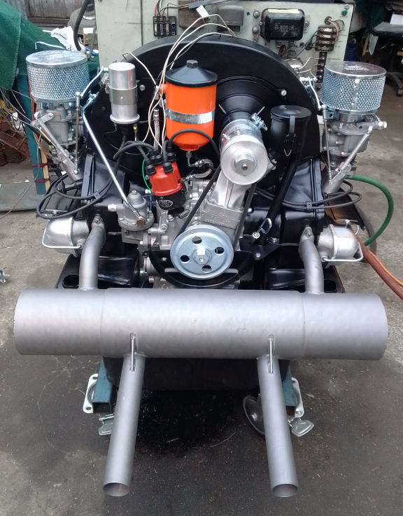
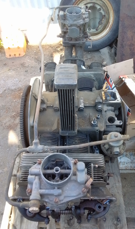
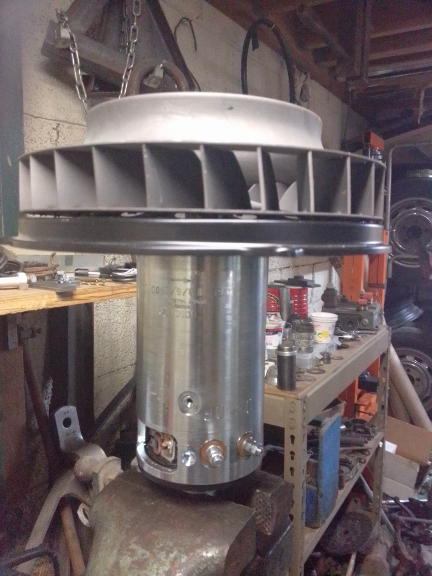
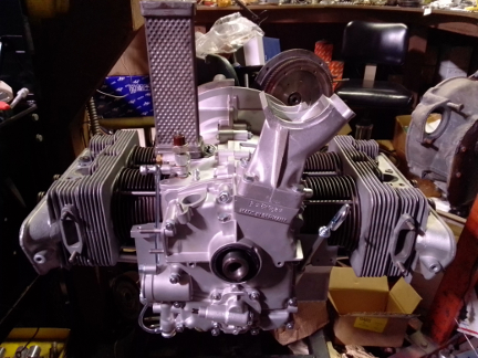
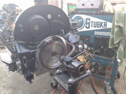
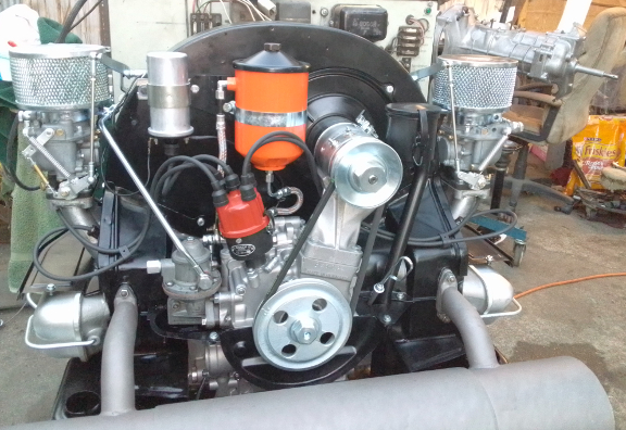
AT RIGHT: This engine on our dynamometer after most of the work described here was performed. Note that in this image, both the distributor and fuel pump were "loaners" just to get the engine run-in while those two parts were being reworked. Said re-working was successful of course, and the parts installed - the whole story is found below.
 This
engine was rebuilt for a customer's Speedster which has a significant racing
history. Unfortunately it's not the original the car came with from new, but
it's very close.
This
engine was rebuilt for a customer's Speedster which has a significant racing
history. Unfortunately it's not the original the car came with from new, but
it's very close.
This engine is period correct except for a few "upgrades" and has just undergone a complete overhaul.
The upgrades include:
Every detail about the engine has been attended to, as outlined below; nothing was left unattended to. In addition to what's explicitly covered on this web page, we also performed every step outlined here.
 This
engine has no particular known history. The current owner bought it as the closest
match they could find to the one that came in the car new. ... This is not unusual,
however, there are sometimes other options, such as a
replacement case.
This
engine has no particular known history. The current owner bought it as the closest
match they could find to the one that came in the car new. ... This is not unusual,
however, there are sometimes other options, such as a
replacement case.
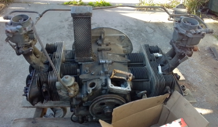
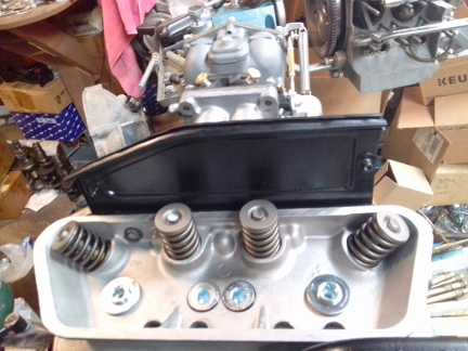
AT RIGHT: Here's the engine ALMOST as it was upon receipt. When the customer left, the very first thing we did was realize that the plating work that would happen soon would need to be applied to the fuel line and, while original, it was somewhat bent up. SO, we mounted up the carburetors, which were in the box adjacent to the right head, removed the banjo bolts and began fitting the fuel line to the pump and carbs the way it should be. It's FAR better to do this BEFORE plating than afterward!
And, here's a tip: Use an adjustible wrench fitted to the flats of the banjo fittings to tweak them so they're parallel and in alignment with the holes they have to mate up to. This gets you great purchase and you can do subtle tweaks this way. In the end, the banjo fittings must mate up without any stress whatsoever anywhere - you can thread in the bolts into the ends you've finished, then move on, but always come back to them to double check and DO NOT use the fitment using banjo bolts to do your tweaking! (It's much harder to do that way!) ... This whole job took about a half hour.
Oh, and there were no air cleaners provided - we'll be sourcing them for the customer.
The original was a normal, and so is this one, but as the original was raced, this one is being "upgraded" to a Super, but with modern specs, such as big-bore cylinders...
During disassembly, a number of items caught our eyes, and so here we have a few photos...
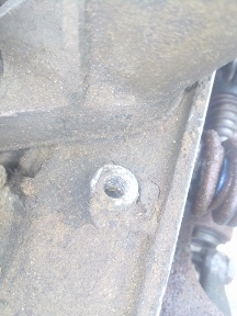
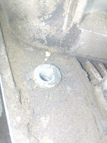
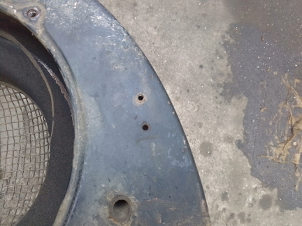
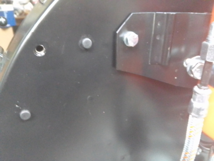
BELOW, ALL: Here we have three of the four M6 sheet metal screw holes that retain the left and engine bay right closing panels as suspect. We won't know for sure if they're stripped until things are cleaned, but these aren't looking good.
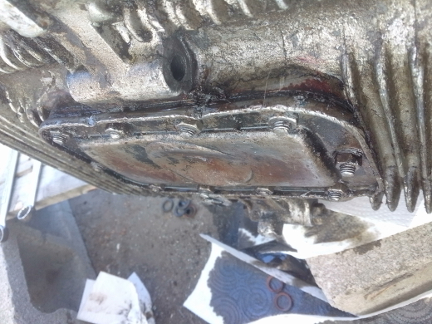
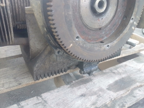
BELOW, LEFT & RIGHT: On the left, there's the oil sump plate, badly disfigured but still doing its job. ... We wish we'd have paid more attention to this damage as later it was a clue we overlooked which could have saved us a lot of time. On the right, the flywheel, which is 180mm and will have to be switched (as discussed below) for a 180. And, note, the lower right stud that attaches the engine to the transaxle is missing.
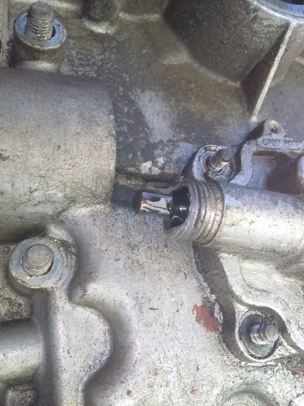
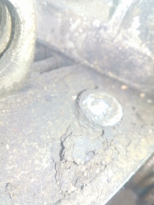
AT RIGHT: The tachometer drive was covered over by a cap made up of an old cable nut and a bit of a rubber nipple - looked like it was from an old eye-dropper. Once that was removed, we found the damage to the threads, seen here. Note how the end of the casting where the cable goes is broken and the outer (here, left-most) three threads are missing.
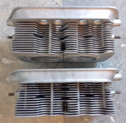
The longblock was pretty typical in most regards but the heads were, unfortunately, from an older engine, and had all brass valve seats which had to be replaced. Also, there was a cracked valve guide boss that had to be welded, and someone had tried to "hot rod" the heads but didn't know what they were doing.
The combustion chambers had been "opened up" in ways that were unhelpful and the engine would not be capable of producing reasonable compression ratio, so, it was decided to prepare them for later pistons that receed into the heads further, thus restoring a reasonable compression ratio.
They had also used ALUMINUM VALVE KEEPERS?! WOW! I've never seen that before. The AL retainers, yes, and, by the way, they're a liability; if you didn't install them from new, you have no idea how much service they've seen and AL parts in key applications like this have finite lives and if one lets go, you have a complete engine loss on your hands - it's just not worth it. If racing? Sure, risk it if you want, but for a non-racing engine? It's a crazy thing to do.
So, the engine got all new valve retainers and valve keepers. And, the valves didn't turn out to be any good anyway - too much wear on the valve stems - so they also were replaced!
 Crankshaft
and Connecting Rods
Crankshaft
and Connecting RodsWe got the rods and crankshafts in process straight away, before the case even.
We didn't take the time to photograph the crank or rods as they came out. The rods were A series and we knew we wouldn't be using them again. And the crank has to get magnifluxed to ensure it's not cracked. So, we just mopped them down and put them in the cycle for the next batch of cranks and rods to be done - of which there were already several cranks and several sets fo rods already waiting, so it was time to initiate processing of another batch of each anyway.
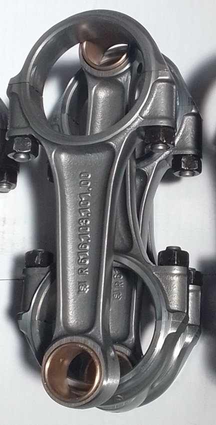
AT RIGHT: Here are the rods, ready for assembly. The rods have been upgraded to the superior B series type. The A rods are known to be "thrown" more easily than the B series. We refuse to build any 356 pushrod, non-roller crank engine with a rod earlier than the B if it is to have anything more than 1600N output - it's just not worth the risk. Could we make an exception? ... Ask us, and we'll think about it.
For us, "rebuilding the rods" means to:
This is all standard work so there aren't any photos of them in-process.
Meanwhile, as hinted at above, there's no way a competent shop would run those early rods in an engine like this - they're a liability! Porsche itself realized there was an issue with the rods and so, now in retrospect, we can say there are three basic versions of rods for the 356 pushrod engine. We selected a set from the middle-type as this engine won't have a fully counterweighted crankshaft or other later high-HP, high-RPM features, so the middle type ("B series") is just fine. And, of course, we "rebuilt them" as described just above.
Following magnifluxing the crank and finding it not cracked, it was a "10/10" (that is, first undersize on both rod and main journals), and as the rod journals were a bit low, we had them ground so it's now 1U on the main journals and 2U on the rods, or "10/20" for some of us.
 Following
the rods being reground, it was balanced, polished, then thoroughly cleaned.
It's pictured here following that process but before the main bearing and gears
were fitted.
Following
the rods being reground, it was balanced, polished, then thoroughly cleaned.
It's pictured here following that process but before the main bearing and gears
were fitted.
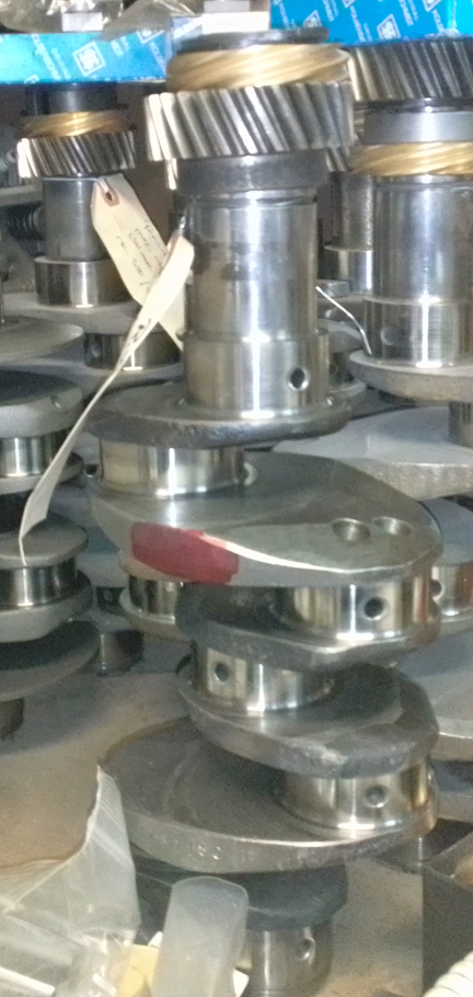
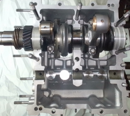
AT RIGHT: Here's the crankshaft, ready for assembly. (The gears on top of the cranks are for the camshaft and distributor/fuel pump and the blue boxes are rod bearings.) Both the rods (as noted above) and crankshaft have been upgraded to the superior B series type. The A cranks are known for cracking somewhat more easily than the B series.
We had intended to take photos of the crankshaft in the crankshaft stand, and
with rods hanging from it, but we had a surprise customer visit and he wanted
to watch, and so somehow taking those photos were overlooked, as shortly, the
whole case halves were going together!
The crankcase was in pretty good condition, but had an M6 sheet metal cheese-head screw broken off in the tin and flapper box mounting location for cylinder. And, important for our customer, had lots of ancient, left-over, sloppily applied case sealant cemented as drips all over the outside of the case. And, it needed an align-bore.
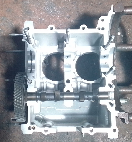
As the customer had asked we deliver a "concourse restoration" we knew that the sealant drips would be an issue so we got permission to expend extra effort to clean this up, and, it was a considerable effort. Here's the results after both cleaning and align-boring - nothing less than stunning:
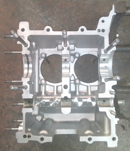
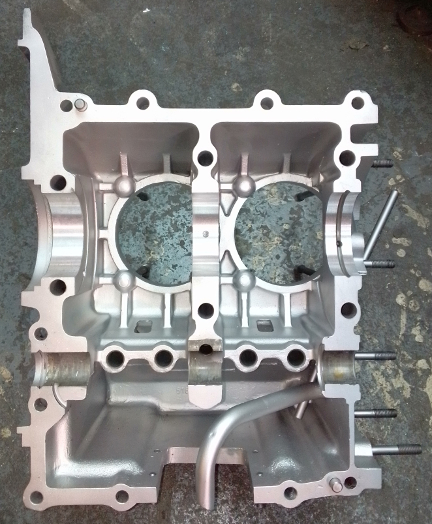
ABOVE, LEFT & RIGHT: Note the lifters already installed in the left half. ...The left half, when in the engine stand, was hard to get a good photo of, so it was moved into the sunlight, which was maybe better, but washed out the image; it actually looks more like the image of the right half. IMPORTANTLY: Note how both halves are different from one another regarding oil supply for the middle main bearing (#2). Both use a dowel pin in what here looks like the dead center. The dowel pins retain each bearing half from moving in the case. However, only the left half (here, the left image) also has an oil hole above the dowel pin. So, how is the right-hand bearing lubricated? As important, with only one oil hole, wouldn't this leave two rods with half their oiling? The answers are provided here.
 As
noted above, the case needed an align-bore. The main bearing bores were standard
and are now first oversize (nominally 60.5mm). Additionally, as hinted at in
the caption to the above two images, the original type main bearings are no
longer available and have not been made new for perhaps 40 years. Eventually,
all the existing stock has been used up, so we had to perform the steps outlined
here in order to take a set of modern production bearings and modify them
for use in this engine.
As
noted above, the case needed an align-bore. The main bearing bores were standard
and are now first oversize (nominally 60.5mm). Additionally, as hinted at in
the caption to the above two images, the original type main bearings are no
longer available and have not been made new for perhaps 40 years. Eventually,
all the existing stock has been used up, so we had to perform the steps outlined
here in order to take a set of modern production bearings and modify them
for use in this engine.
The result is as you se here, left and right - the left image here is from the left crankcase half and the right image in the right half.
What's notable here is that if one looks at the images above, one can easily see that the right case half's "center" main bearing (number 2), which is necessarily a two part bearing, only receives oiling from the left case half. And, there's no other provision for oiling to reach the right half except via the bearings, which are no longer available (but are pictured on the web page cited just above). And so, here we have modified modern production berings to provide that oiling like the old bearings did. (Again, see the above cited web page for details.)
Of course, the lifters were re-faced (four showin the left half image above and below) and the cam was replaced with a re-ground S (seen below).
It was intend to here be shown the case half with all the guts, ready for the two halves to be assembled. However, it tuned out that the only photo that we got of the camshaft, showing that it's parkerized (a dark, black-looking color is created by parkerization) following grinding, is from a shot we had de-selected! Now, we have to re-select it, so you get two images insted of one! ... Oh well, we're better engine builders than photographers or web site builders!
Yes, the lighting makes it seems almost as if these are different crankcases! And, check out the reddish glow of the next image, too! But nope, it's all this same engine; lighting can do weird things sometimes.
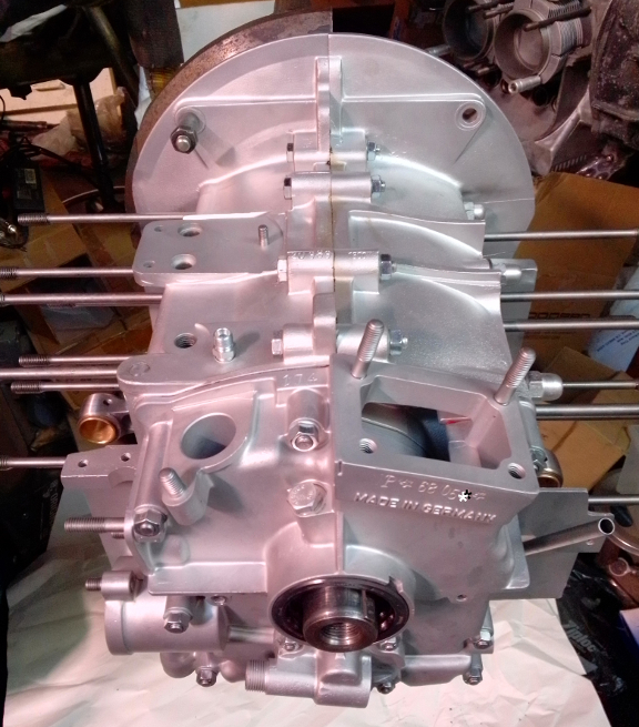
So, now it's time to seal up and attach the two halves, install the timing cover, then "button it up," to keep out dirt and prepare for the top-end assembly. So, on go the pulley seal, oil pump, sump plate, and so forth. Quickly we have this:
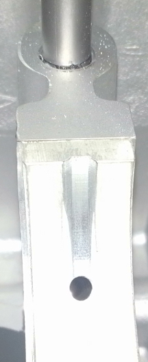
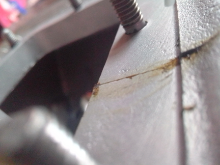
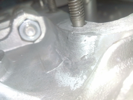
However, as has happens sometimes, we don't notice flaws until late in the process. And so it was that this crack wasn't noticed until installing the sump plate.
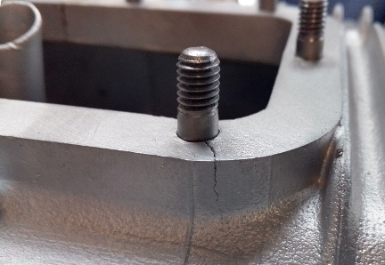
Damn! How annoying! If we'd found this earlier, it would have cost us less time... Basically, the whole build had to start over, but notice this other, no doubt related issue: The plane of the oil sump is also disturbed! Ouch! And, this also explains why the oil sump was damaged so badly... Given the damage, it's easy to understand how a driver must have struck some kind of foreign object on the road right on the edge of the sump plate, trashing the plate, cracking the case at one sump stud and disrupting the sealing plane where the sump plate mounts.
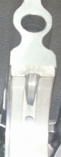
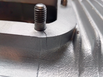
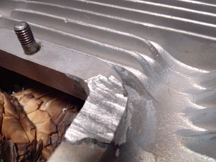
BELOW, LEFT & RIGHT: Here we see the plane of the oil sump gasket, screen, and closing plate where the two halves mate. On the left, the forward surface has a notable step. Note that the step on the inward face doesn't matter and is extremely common; it's the other surface, the one the studs thread into, that matters as that's where it all gets sealed up! In sharp contrast, note the image at right, which is the same location just on the rear of the sump opening - there, the two levels are virtually perfectly aligned along the sealing plane.
The fix was straight-forward as one might expect.
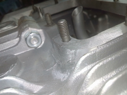
Of course, the stud was removed, the crack ground out, re-welded, the outer surfaces refinished, the stud hole re-bored, and we got on with it a second time! This was a huge and not-welcome delay, but we'd never before seen a crack like this, so we weren't looking for it! Well, chalk up one more thing to be aware of! ... Here are some images of the fix:
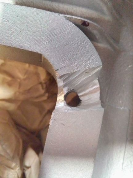
BELOW, LEFT & RIGHT: At left, the stud has been removed, of course, and the crack ground out. Nothing of the crack can remain or it will resume and propagate in the future, like some weed whose roots you didn't remove!
With the crack fixed, the case was reassembled and now we pick up more or less where we left off! --WHEW!--
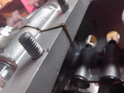
BELOW, LEFT & RIGH: Here we have a parting shot at the crack repair.
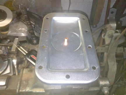
NORMALLY, we don't install the sump plate until after the rest of the engine is done, just in case something falls in, it's a little faster to get it out, but that's a rare event and we wanted the sump "behind us", plus, with a brand new zinc-plated sump plate, it's rather beautiful! But first, of course, we had to install the magnet on the plate using a special copper rivet - and, notably, we happen to have the correct tool to "buck" the rivet!
BELOW: The new sump plate about to receive the magnet, copper-rivet at the ready. Note that the rivet is set into a special tool that's mounted in the bench vice. It's cupped to match the curve of the rivet head exactly, and that's why the plate and rivet can be perfectly balanced thereon.
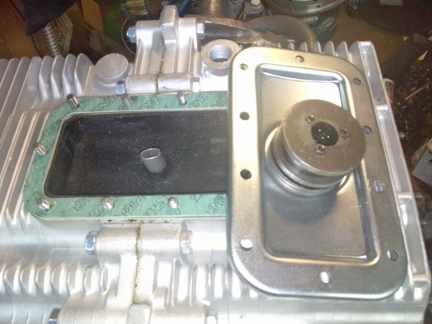
And now, install it! ...Because of the small step at the forward end of the sump opening where the left and right halves meet, we layed down a layer of "Aviation gasket" - the same stuff Porsche and VW used to seal their case halves on assembly-line engines - and "glued" the upper gasket to the case. This gasket should be left in place when cleaning out the sump!
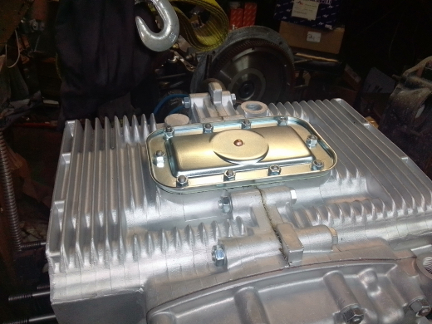
BELOW, LEFT & RIGHT: The magnet installed on the plate means the assembly can be completed; if someone wants to paint the sump plate, that can be done at any time, but we thought the new, zinc-plated sump plate is rather beautiful like this!
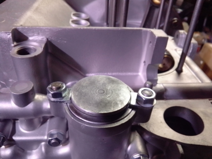
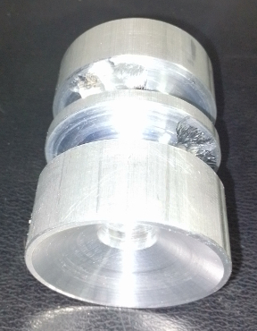
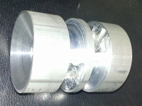
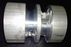
The oil thermostatic system was introduced and retired from service all on one year, 1958, so this engine has the casting for it, but it also has the "delete option" wherein there's just a simple AL cap that closes off where it had formerly been installed. The problem with this is that it creates a relatively huge void which must be filled every time the engine is started BEFORE the engine will develop oil pressure, and the hotter the engine, the faster it will leak down yet the more vital it is. So, we created a filler plug to take up a substantial percentage of the void and thus dramatically shorten this oil-starvation period.
BELOW, ALL: Here's our aluminum plug that fills the void the thermostatic oil control valve once occupied. At left, that's the oil input end from the pump. From there, it flows into the plug an feeds to both of the two grooved areas, one of which goes to a pressure relief plunger ("oil control piston", and the other goes to the oil cooler and bearings. The piece has these big radial grooves so that the rotational position doesn't matter as otherwise the piece would have to be locked in a particular rotation - this was both easier to make and less risky, though it perhaps could take up a bit more volume with a different design. Oh, and not pictured here, we also took the opportunity to improve the O-ring design at the end where the cap goes.
And, here it is, installed. Notably, the O-ring that is normally provided for this purpose doesn't give us any confidence that it'll be leak free as it's of insufficient cross-sectional area, in our view. So, we used a thicker ring.
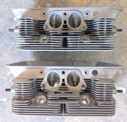
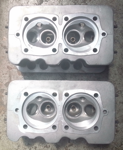
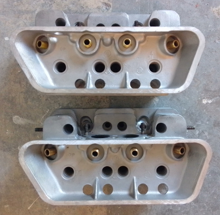
The heads were, in our words, "a bit of a mess." After the owner learned of all the steps to getting the heads ready for installation, he deided instead to opt for a pair of 912 cylinder heads. Well, OK, we can do that.. They won't flow as much as they would on the engine they were designed for, but that was deemed acceptible as they will do better than the A heads, even here, though no driver could tell the difference.
Of course, they got all the usual treatment - all new guides, crack, seat replacement and thread repair where needed. And a flycut-and decking to ensure they'll seal properly.
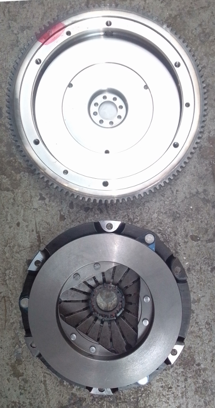
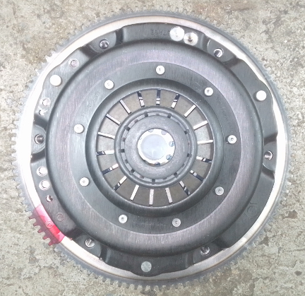
Since the banning of use of asbestos in the mid 1990s, the 180mm clutches have been inadequate for anything but the lowest output engines, so an "upgrade" to 200mm unit is, as a practical matter, required. So, we secured all new parts, of course, then balanced the flywheel by itself, then with the pressure plate as a mated pair.
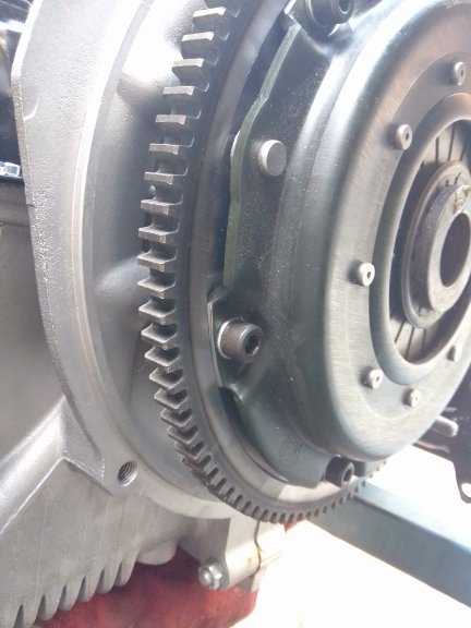
BELOW LEFT & RIGHT: On the left we see the two parts separate from one another with friction surfaces exposed. The "notch", or recess just outboard of the pressure plate mounting holes is a key indicator that this flywheel is set up for the earlier style pressure plate. On the right, we see the two together. Notably the "release plate" where the throw-out bearing contacts the pressure plate is removable and so THIS pressure plate can work with either the early style transaxle throw-out bearing or the later version which uses a guide tube for the bearing. Of course, the release plate is installed so it can be used with the 1958 transaxle.
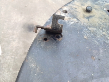
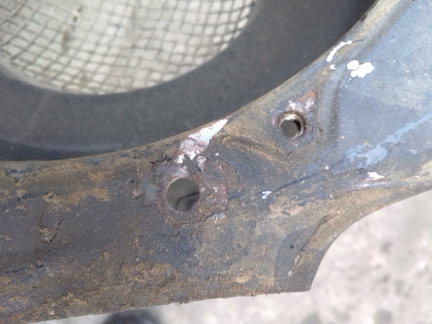
Normally we don't have a section on fan shroud repair, but here we do! The fan shroud had a few problems, primarily five holes drilled into it (with some foreign bracketry still attached, and a torn-out weld-nut for the upper cylinder shroud for cylinder 2. Here are the problems and the fixes.
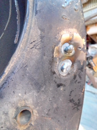
BELOW, TWO ON LEFT & ONE ON RIGHT: At left we see the "before", with a bracket to remove, then the holes that have to be welded, and then on the right the welded-up holes, but before refinishing.
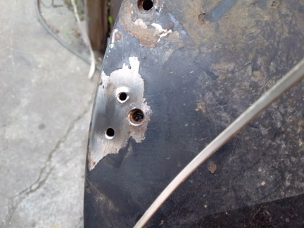
BELOW LEFT & RIGHT: Here we see the matching damage and repair from the right side, again before refinishing post-weld.
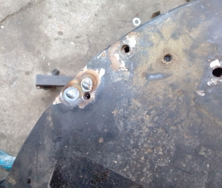
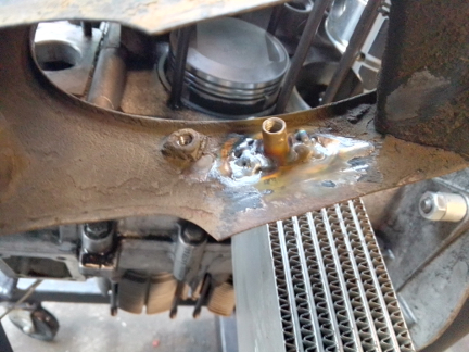
BELOW LEFT & RIGHT: Here, we can see the weld nut for cylinder 2's upper shrouding is missing, and on the right we see it has been replaced. Sharp-eyed readers will note that the background is, indeed, another engine going together that happens to be visible through the holes in the shroud! ...We were just looking for a place out of direct sunlight to take the photo, and everywhere you turn is another engine!
Mounted to the fan shroud are a number of components.
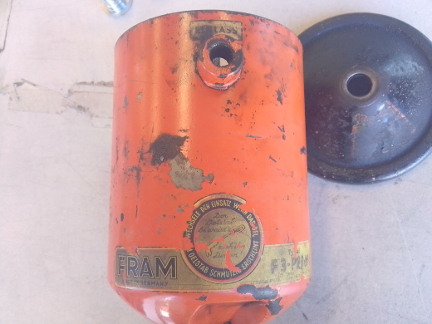
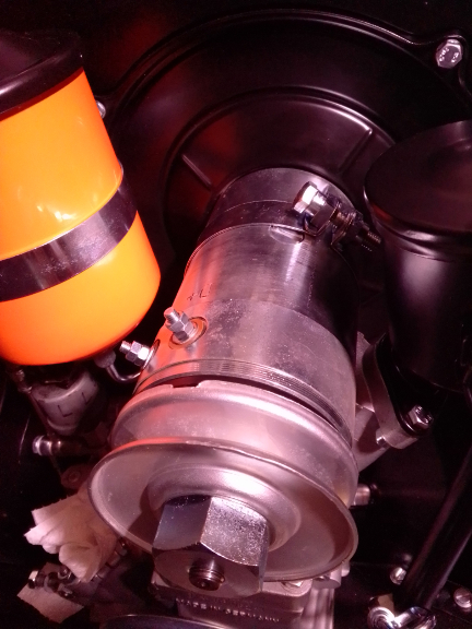
BELOW: Here's the original oil filter canister, showing decals and their placement.
 We
took the core generator and rebuilt it.
We
took the core generator and rebuilt it.
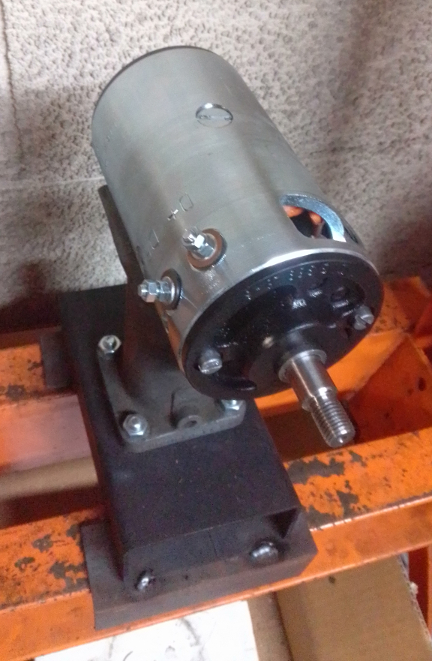
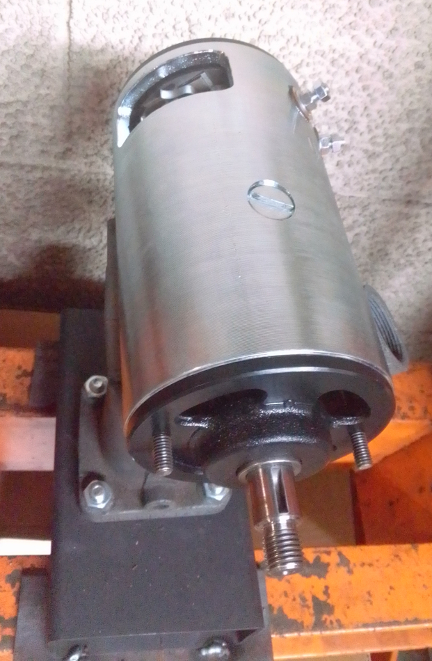
AT RIGHT: This generator begins reassembly.
In order to not make this web page so filled with images that it takes too long to load, please check out this page where we describe the process in more detail and with more images.
BELOW, LEFT & RIGHT: A generator is not really a hard thing to rebuild, you just need the right tools and the right replacement parts when needed. Of course, all new bearings, brushes, etc. And, in this case, new arbor and field windings, too!
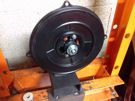
ABOVE AND RIGHT: Here we have the arbor and backing plate mounted then the fan is mounted and adjusted (with shims). Not seen is the arbor for the puley as it's in the vice, providing a grip for tightening the fan nut! New woodruff keys were installed, of course.
We just forgot to take images of it in progress, but we rebuilt it - new diaphragm, etc, and a lot of the pieces replated, though not everything.
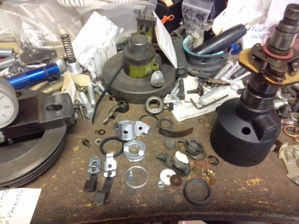
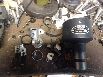
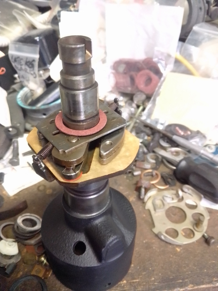
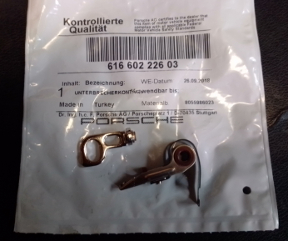
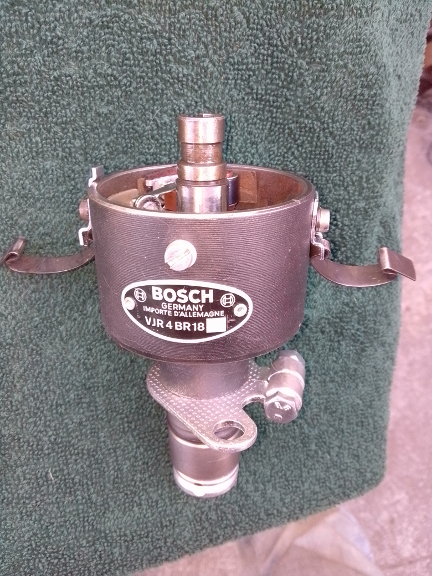
We sourced a good, correct for 1958, Bosch BR18 distributor and rebuilt it. Here are some photos of that process.
We apparently didn't think to take any photos of the disassembly, or preparation of the housing. Instead we pick it up where the ID badge has just been reinstalled with new rivets (by the way, it came with this same type of rivet, not the earlier rounded head version). And, we'd already replated a lot of the little pieces as can be seen here.
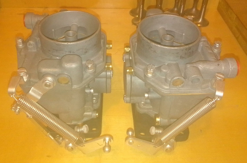
These carburetors are Zenith NDIX series, which have several sub-varieties. This version is for normals but has been "upgraded" to the "Super" version via the change of venturi and some jetting. (There's another version used on the C series.)
Here they are, ready to be mounted:
 The
carbs were thoroughly gone through and rebuilt. Here are the details of the
deficiencies of the cores:
The
carbs were thoroughly gone through and rebuilt. Here are the details of the
deficiencies of the cores:
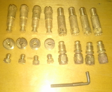
ABOVE RIGHT: These are the Normal ("Damen") jets we took out, and the worn out left-hand-thread pump link cited in the list above.
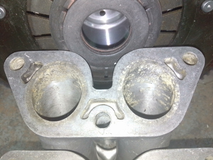
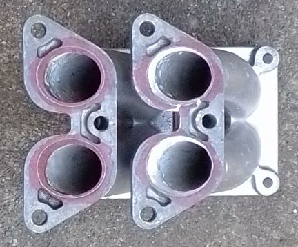
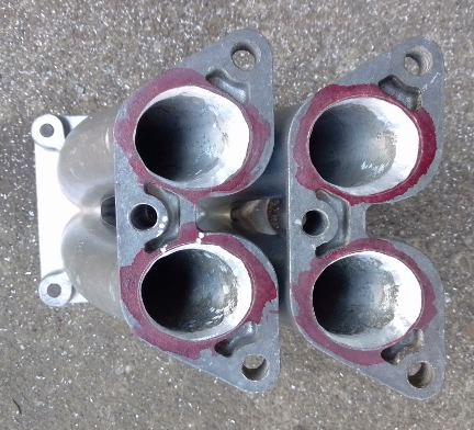
The intake manifolds had to be "port-matched" to the heads - both the original A heads and the 912 heads chosen later have the late type port shape.

 Due
to the previously fitted A heads that had been inadvisedly "opened up"
in a way that meant the engine wouldn't make a good compression ratio, we switched
to late pistons which fit more deeply into the heads, thus bringing up the compression
ratio back into the normal region. Then, when the decision was made to switch
to 912 heads, this fit in just fine. ...They're NPR Big-Bore (86mm) copies,
pistons balanced as usual.
Due
to the previously fitted A heads that had been inadvisedly "opened up"
in a way that meant the engine wouldn't make a good compression ratio, we switched
to late pistons which fit more deeply into the heads, thus bringing up the compression
ratio back into the normal region. Then, when the decision was made to switch
to 912 heads, this fit in just fine. ...They're NPR Big-Bore (86mm) copies,
pistons balanced as usual.
We measured the cylinder spigots in the case and found them wonderful - "Normals" (the Germans call 'em "Damen") typically have an easy life.We then checked the cylinder installed heights for matching their neighbor. The book tolerance is 0.1mm (four thousandths of an inch). We were delighted to find that both pair were of identical installed heights! Unfortunately, we forgot to take a photograph of this check.
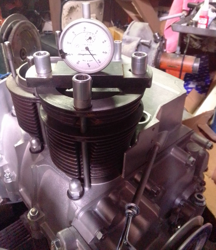
AT RIGHT: With the rings removed, we do this CAC check - Crown Above Cylinder - which, so far as we know, we are the only shop that measures piston height this way. It's superior to the liquid method because this gives the data that permits us to simply move pistons around and improve the build (so that all cylinders produce the same amount of power) without removing material.
Of course, we do this to all four.
Oh, of course, we allways match pistons to cylinders and match piston weights as a set before installation. By shuffling around the piston pins among the pistons, this set naturally balanced (without removing material) to within 0.6 grams - the official specification is ten grams (10g).
 So,
we then did our usual CAC - Crown Above Cylinder - measures as shown here, and
with the head CC volumes known we were able to promptlly set the compression
ratio (in this case it's right at 9.0:1) and move to final assembly of the heads
onto the bottom, thus making a long-block. Of course, this meant installing
the pushrod tubes and lower cylinder air deflectors and then torquing them on.
So,
we then did our usual CAC - Crown Above Cylinder - measures as shown here, and
with the head CC volumes known we were able to promptlly set the compression
ratio (in this case it's right at 9.0:1) and move to final assembly of the heads
onto the bottom, thus making a long-block. Of course, this meant installing
the pushrod tubes and lower cylinder air deflectors and then torquing them on.
AT RIGHT: Officially speaking, it needs the flywheel and rocker gear mounted to be a long-block, but close enough for now!
Anxious to complete the engine, things proceeded from here as quickly as can reasonably be done, but there were fitment issues. This is normal for parts that have never been together before. The tinware tends to get bent and otherwise damaged along the way and it all needs to be tweaked so it all fits at the same time.
We won't bother to note all the fitment issues, but here are two examples that photographed well that can serve as examples.
AT RIGHT: The thermostat mounting bracket has become "compressed" (bent) considerably. We'll bend it to aproximate position later, when the assembly is more complete as by that time we'll be able to figure out reasonable alighment.
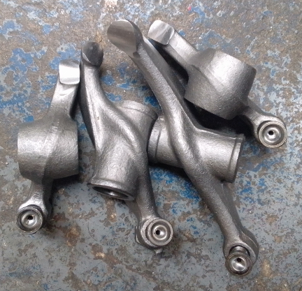
We also still had to install the rockers - we blasted them clean then refaced them, of course. Here's one side's worth.
BELOW, LEFT & RIGHT: Here are the rockers for one side, ready for mounting, and the head, ready to receive them. Even though these are early rockers, they usually work with later heads, but not always. we'll do a final check to ensure they operate throughout their entire operating range before calling it done.
The fan shroud got the original rubber plugs going in the dis-used screw holes instead of plugging them with screws, while the generator got the later style brush cover since 1958 was an either / or year.
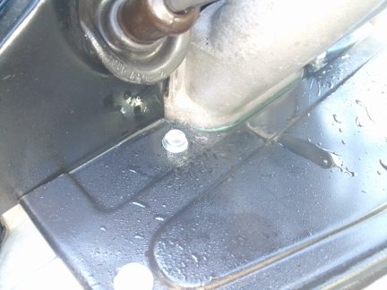
And, when it was time to install the clutch and mount the engine on the dynamometer, we noted that the lower right engine to transaxle stud was missing!
Meanwhile, the distributor and fuel pump needed attention, so we'll now segue to them.
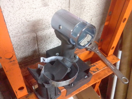
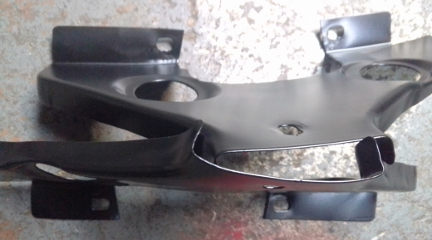
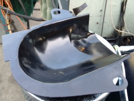
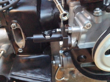
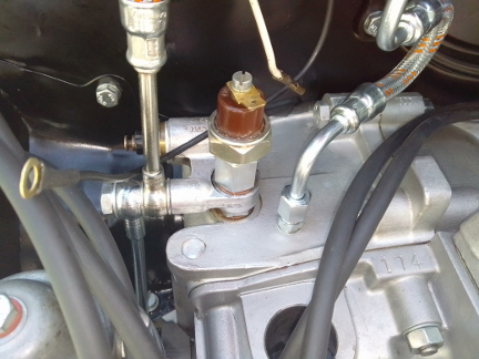
The pulley shroud was lost and replaced by our customer who provided a younger, late C era version that had a big hole in it that someone had welded closed. Well, OK, so we powder coated it, then, because it's not intended for this few-months-only, 1958 model year "thermostat" oil system, which has a vertical pipe running from the oil junction block to the lower oil pressure control piston, it had to be "clearanced," as shown. Then, the fuel pump spacer / adapter is installed and the pushrod length checked. It turned out that the "bakealite," pseudo plastic spacer / adapter with cast-in metal threads was cracked, as most are, and so we switched to the slightly younger, mostly metal version which only uses a spacer for heat isolation and not as a fuel-pump adapter.
BELOW LEFT & RIGHT: At left we see the a small bit of the pulley shroud about to be completely removed to provide clearance for the vertical oil pipe only used for a few months in the 1958 model year. At right, we see the fuel pump mouting location occupied by the aluminum version of the adapter portion of the assembly and a barely-visible "bakelite" (dark brown) plastic spacer, followed by the factory tool used to measure the extent to which the fuel pump pushrod moves and its maximal and minimal positions, all of which must be in specification.
 Around
this time the cork gaskets had likely cured onto the valve covers, so a final
valve lash check was performed and then the valve covers installed. Then, attention
turned to the few ancilaries remaining, such as the routing of the spark plug
wires, etc.
Around
this time the cork gaskets had likely cured onto the valve covers, so a final
valve lash check was performed and then the valve covers installed. Then, attention
turned to the few ancilaries remaining, such as the routing of the spark plug
wires, etc.
As is extremely typical, the drop links and vertical up-link that gets the throttle input up and over the fan shroud and to the carburetors had screwed up female sockets and their shafts had also been roughly handled over the decades. This is so common, we stock them, so we just put on a new set.
Pretty soon we had the engine ready for the exhaust. We had sourced the only muffler manufactured for this engine type by Liestritz, Porsche's chosen OEM, and mounted it.
The customer then informed us that their vehicle has the "delete option" for the stock exhaust going through the bumper and instead needs the "sport muffler." We informed them that that didn't exist when their car was made, but they said that's what they wanted, so that's what we've provided, as seen below.
At this point, the engine assembly is at it's zenith and it's just a matter of chasing any leaks, and any other remaining niggling little details.
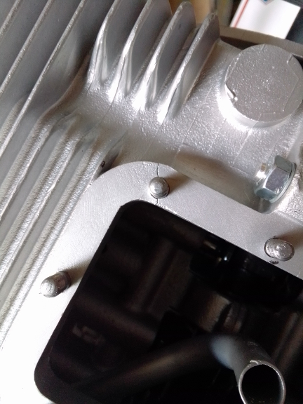
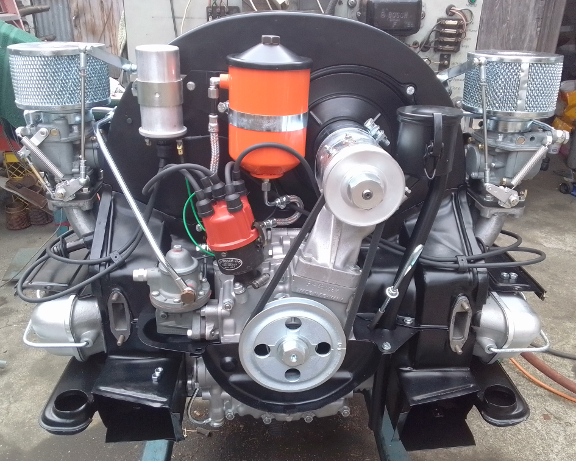
AT RIGHT: Here's the engine as we ran it in. As normal, we didn't even think of doing a high-performance run to see how much HP it produces because that should never be done on a freshly assembled engine in which longevity is desired until it has at least a thousand miles on it, the longer the delay the better up to say, 3000 miles.
Prior to the run-in process, we ran the engine and checked the carburetor jetting, set ignition timing, set idle, checked for leaks, made sure it returns to idle, even when hot (takes a few seconds, but it comes down to a nice idle) and so forth.
We noticed during run-in that the oil pressure was, even after 30 minutes of running (with a fairly light load) reaching the maximum permissible for the early system (4 atmospheres, about 60 PSI). This was clearly due to the oil simply not being hot enough yet to thin out combined with around 2500 rpm. There's little modern experience with the dreaded oil thermostat system, and it's not well known what the "delete option" of the thermostat does to oil pressure throughout the dynamic range of the engine's speed and temperature.
There was a total of a couple hours of run-time on it by the time the run-in was completed, and three valve adjustments had been performed: one at assembly, and one right before and right after run-in - stone cold, of course.
After run-in, we de-installed our oil pressure gauge sending unit and installed a new screw contact type. But because we still wanted to run the engine a little to help ensure we resolved a fuel pump leak, we installed a spade connector so the "idiot light" continues to work on the dyno.
When we did the final fuel pump leak check, whoops! The oil cooler burst!

We promptly realized this was oil and where it was coming from so we pulled the shroud and sure enough, the oil cooler had sprung a leak.
One might suspect, incorrectly, that the cooler burst due to over-pressure and speculate that maybe a thin single-weight oil could be used to avoid this? But it turned out not to be the case. First, during run-in the highest pressure noted was four bar (four ATU, that is, four atmospheres, which is about 60 PSI), which is the rated upper range of the oiling system. And, as the following image illustrates, the oil cooler had not actually popped from over-pressure. However, we had to replace the oil cooler with something so we replaced the cooler with a younger version, designed for the higher-pressures of the later, much larger oil pump - the late system is rated at about double the pressure of the early system.
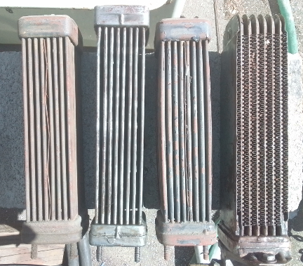
AT RIGHT: Here we have four oil coolers lined up for comparison. The one that was installed that failed is the second from the left. It is flanked on its left by an undamaged cooler that's designed for this same early pump system, and on its right by a cooler that did suffer over-pressurization - it's puffed up like a balloon! As can be seen, the failed cooler did not suffer this over-pressurization. And, on the far right, we have an example of a cooler intended for the vastly larger oil pump system that was introduced in 1960 which can take around double the pressure.
There are not less than four versions of this later cooler, only one of which has the smaller, 6mm mounting studs, so that's the type we installed here.
After the oil cooler was replaced, we ran the engine to ensure this one didn't leak, either! And this was a perfect opportunity to be reminded that any time the fan shroud has been dismounted and remounted, the throttle arms likely need re-adjustment (!!), which they did this time, too.
AT RIGHT: One step left: Paint the tops and bottoms of the air cleaners the correct silver as we previously had painted them the color used on later air cleaners by mistake... Other than that, this is as "delivered" to customer. Note also their transaxle in the background on the right of this image!
Of course, when the customer came to pick up the engine, they complained we had the wrong muffler installed.
They had discovered that what we'd told them was in fact true (though we got no acknowledgement we were correct), they were going back to the stock muffler, and wanted us to remove the sport muffler they'd asked for and they'd take no muffler.
That would have stuck us with TWO mufflers we'd secured for this customer. So Chris, who was managing this for us, switched the two for them. Chis, who was caught off guard about this, let them get away with not paying for our overhead on this other (stock) muffler (especially the substantial freight that was built ito the price). And, it's of course not appropriate that they stick us with a now USED sport muffler that we have nearly $1000 out of pocket for, but some customers don't respect their vendors. I suppose it's up to us not to let that happen again.
Because some people are keeping logs of VIN and engine numbers and then purport to tell people what someone else has, out of respect and concern for a buyer's privacy, exact VIN and engine number data are not published here.