Copyright © 2007 - 2025, Coachworks For contact data Click Here.
Copyright © 2007 - 2025
Copyright © 2007 - 2025,
Coachworks For contact data
Click Here.
![]() has been retained for reference purposes.
has been retained for reference purposes.
 Porsche
Engine for Sale:
Porsche
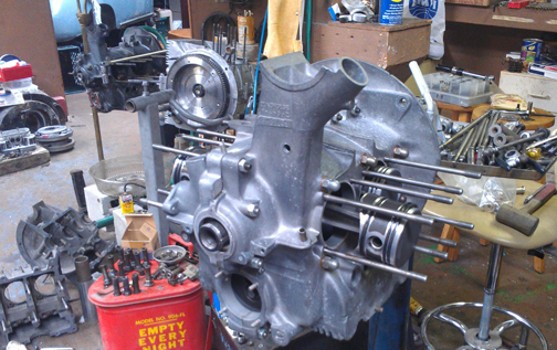
Engine for Sale:This engine, in long-block form, is ready for pickup or delivery today.
SPECIAL NOTES
This engine is available already "run-in" as per Porsche factory specifications as outlined in the Workshop Manual, "Running-In and Testing" operations, 43 EN and 44 EN, pages E51 and E52.
ALSO
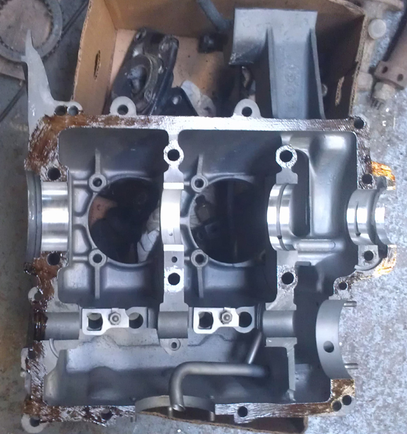
The correct (vented with wire-mesh screens) valve covers
are now fitted, as imaged above.
A different (non-vented) pair were fitted temporarily and can be seen in
some images below.
 This
1953 356 1500cc engine is completely stock and correct, has new pistons and
cylinders and has just undergone a complete overhaul, and is fully
balanced for smooth running, long life, and a few more HP.
This
1953 356 1500cc engine is completely stock and correct, has new pistons and
cylinders and has just undergone a complete overhaul, and is fully
balanced for smooth running, long life, and a few more HP.
The crankcase is "numbers matching" and is in very good condition. The crankshaft has been upgraded to the "B" series, which are less prone to cracking. It is fitted with new, original-size pistons and cylinders.
Every detail about the engine has been attended to, as outlined below; nothing was overlooked.
I obtained this engine as a long-block decades ago, and kept it on my engine shelf where it has sat until recently. The earlier history is completely unknown, but many people have seen this engine sitting on the engine shelf in my workshop, so you could perhaps jokingly call it a "well known engine!" (I have several like that!)
This engine has never been more than a long-block in all the time I've known about it, and I have never attempted to run it during all these years. About all I ever did with it was disassemble it in stages.
In late 1990, if I recall the year correctly, Richard V. Lukes (of Lukes and Shorman fame) came by specifically to help me go through my early two piece crankcase engines and teach me about them. So, the cylinder heads came off, and we split the case.
We found the engine had suffered a rather amateurish rebuild, but apparently hadn't been run in a great many decades, we surmised, based on the caked on oil sludge, etc. The biggest problem was the pistons and cylinders were shot as a lot of the chrome was worn through. It must have smoked badly! Richie said the engine was lucky because sometimes, when it gets that thin, the chrome gets pealed off in a large curl and, depending on the speed it's running at the time, the engine "explodes" as the piston tries to force the curl into the combustion chamber, or down into the case - it's never pretty!
The rest of the engine was well worn, but otherwise seemed OK. The crankshaft was third undersize on both rods and mains, so it got set-aside, now serving as a door-stop. Richie gave me a camshaft for it - it's beautiful! AND, as it was a used camshaft, he gave me the original lifters he says were run with it, each labled so it goes back in the original location! The rest of the story is provided in the overhaul section below.
The reason I built it at this time was that while I don't have any particular application for it, I just finally decided that it wasn't getting any younger and someone ought get good use out of it.
The first thing to do was prepare the crankcase. OH what a CHORE!
 I
should have cleaned it up YEARS before, back when we could get real solvents.
The parts washers of today just plain don't work in comparison to the old stuff.
DAYS were spent soaking! MORE than 12 hours were spent scrubbing with a modern
"hot" water-based "solvent" parts washer, just trying to
get the crankcase clean! Eventually I got it clean enough to media-blast and
then removed and replaced all the "soft plugs" that plug the various
oil drillings - this was done to ensure that ALL the oil passages are perfectly
clean!
I
should have cleaned it up YEARS before, back when we could get real solvents.
The parts washers of today just plain don't work in comparison to the old stuff.
DAYS were spent soaking! MORE than 12 hours were spent scrubbing with a modern
"hot" water-based "solvent" parts washer, just trying to
get the crankcase clean! Eventually I got it clean enough to media-blast and
then removed and replaced all the "soft plugs" that plug the various
oil drillings - this was done to ensure that ALL the oil passages are perfectly
clean!
Unfortunately, I didn't think to take any "before" photos showing what the case looked like prior to cleaning - if I'd had any clue that it would be this difficult, I would have because it would be very enlightening to see just how long it takes to clean up a mess! If it weren't a rare, two-piece crankcase, I don't think I'd have bothered! However, the image at right shows the hardest area to clean - the casting parting-line that runs horizontally in the sump area. Note how clean it is now!
After cleaning, the crankshaft bore was checked and the average of bearings 1 through 3 measured 60.15 mm, with some spots up to 60.2. This is quite a bit too large but does indicate the case had never been "align bored" before. (Standard on a two-piece crankcase is nominally 60mm). OK, re-bore the crankshaft bore to the next size larger, and maybe two sizes larger, as 60.2 is awfully close to 60.25mm!
Oops! Can't Align-Bore YET!
The bore for the pulley (where the oil-return threads go) supports the boring bar (that in turn supports the cutters) and provides alignment to center on one end (the flywheel seal's recess providing that service on the opposite end), however, the pulley bore was TOO LARGE! And I mean way too large.
I could guess that someone increased the bore on purpose to run a "sand seal" (typical oil seal), but that simply will not do now. But, even more important, there was simply no way to support the boring bar to align-bore the crankcase. In a sense, it's a blessing that the case needed an align-bore because otherwise the very excessive clearance to the oil return threads would never have been discovered until the engine was put into operation - adding quite a bit of effort to the repair! In fact, experience with this engine convinced me that I should always check the pulley bore on every engine as a regular matter of course.
The solution was to add metal to the pulley bore by welding, create a special adapter that fits inside bearing number 4 to support the standard "boring bar", and re-bore the pulley bore to the size of a new crankcase, then align-bore as usual. Thankfully, I have a new old stock crankcase for measure!
I've had to do this a few times, so I created a web page to document the process and help others who may need to know how to do this. Find that page here.
(As a side note, this same fundamental process can be used to re-size all the main bearing bores back to standard! If you need this done, I can do it for you.)
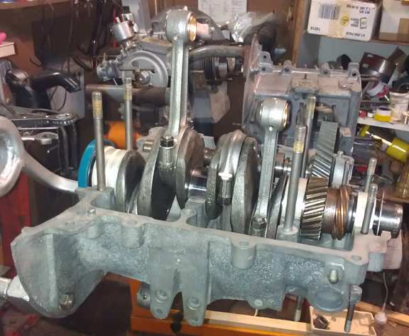
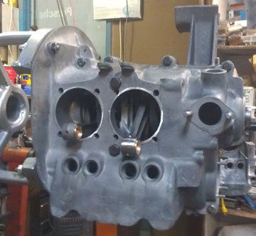
 After
the pulley bore was repared, it was time to bore the crankcase itself. I gave
it a try at 60.25mm (standard for the later engines) and then, if successful,
would use (slightly modified) three piece crankcase bearings because 60.25 is
not (and never has been, OE) available for two-piece crankcase engines. But
the bore didn't clean up. That's to be expected when some of the bore is already
at 60.2mm. So, it went to 60.5, which is considered the "first oversize"
anyway. Here you can see the freshly bored crankcase - or, the right half at
least.
After
the pulley bore was repared, it was time to bore the crankcase itself. I gave
it a try at 60.25mm (standard for the later engines) and then, if successful,
would use (slightly modified) three piece crankcase bearings because 60.25 is
not (and never has been, OE) available for two-piece crankcase engines. But
the bore didn't clean up. That's to be expected when some of the bore is already
at 60.2mm. So, it went to 60.5, which is considered the "first oversize"
anyway. Here you can see the freshly bored crankcase - or, the right half at
least.
Following this, I replated the crankcase, as was originally done, with the Dow 19 process. This process sometimes creates a brownish gold coloration, but in this instance, it just made the crankcase a more consistent grey. The real benefit is that it helps protect the magnesium, wich is very galvanically active.
At this point, the crankcase underwent a "final check." Thankfully, the oil pickup tube is very tight in the case. (It can be challenging to repair a loose pickup tube.) And, all the threads are fine, including the rear-most two, that accept the forward pulley shroud. These are often stripped. Because the outermost thread or two are often not very sturdy due to the use of too-short fasteners and too much torque, I ran a tap through and cut a few more threads just to ensure there's no problem later. (Long M6 bolts should be used here - which is good advice anyway.) And, unusually, all of the sump studs are in great condition!
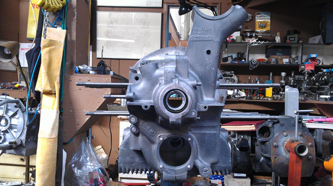
NOTE: In the image above, the weird looking thing inside the crankshaft bore is actually the weld holding the engine stand's arms to the stand's central tube!
Not forgotten, the cylinder "decks" were checked that they are in one plane with their immediate neighbor using a special tool designed just for this purpose. And, there's a reason for thorough checks like this; in this instance, both halves had a low-spot of between three and four thousandths of an inch in the area where the two cylinder spigots come close together. That is, the cylinders would be canted toward each other if nothing were done about it - and, of course, the cylinder head to cylinder seal would be stressed and could leak. The specification is 0.1mm, or, about 4 thousandths - too close for my tastes as it's basically at the official limit. I could have just gone with it, but decided instead to "deck" the cylinder spigots, so the case is ready for long life.
With the poor lighting at the mill, the photos I took of the process didn't
turn out, but in later images, look for the bright rings around the cylinder
spigots!
 As
cited above in the background section, the original crank was third under on
both rods and mains. It also happens that these early crankshafts were more
prone to breaking than the younger cranks are. As I recently disassembled another
two-piece crankcase engine into which I intend to install a Hirth roller-bearing
crankshaft, I selected that crankshaft for this engine becaues it's a "B"
in good condition. It was formerly reground to first under on both rods and
mains (nominally 49.75mm, and 52.75, respectively).
As
cited above in the background section, the original crank was third under on
both rods and mains. It also happens that these early crankshafts were more
prone to breaking than the younger cranks are. As I recently disassembled another
two-piece crankcase engine into which I intend to install a Hirth roller-bearing
crankshaft, I selected that crankshaft for this engine becaues it's a "B"
in good condition. It was formerly reground to first under on both rods and
mains (nominally 49.75mm, and 52.75, respectively).
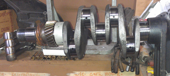
As a first step, I had it magnifluxed to check for cracks and then thoroughly cleaned and polished it. This crankshaft has its mated flywheel - they're a pair, so they're staying together. I had the clutch face resurfaced - there's a lot of life left on this flywheel and the starter teeth are in good condition, and then balanced the flywheel.
I then mounted the thrust bearing and went through the iterative process of mounting and dismounting the flywheel to try different shims to set the end-play. While it can be done later, this work is always better done by using a feeler-gauge before the engine is assembled.
 Next,
after trial-fitting the bearings in the crankcase (there's an image of this
below), bearing three, the two gears that go on the crankshaft, their spacer,
and the lock ring were installed.
Next,
after trial-fitting the bearings in the crankcase (there's an image of this
below), bearing three, the two gears that go on the crankshaft, their spacer,
and the lock ring were installed.
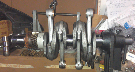
I then pulled out a set of already rebuilt rods, mounted the crank in the crankshaft stand and installed the rods.
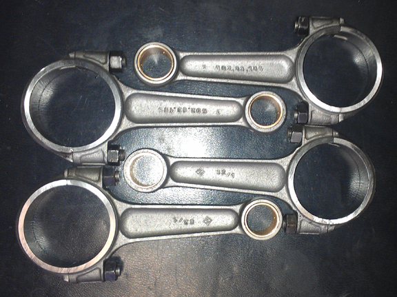
For me, "rebuilding the rods" means to:
This is all standard work so there aren't any photos of them in-process. However, here they are when assembled onto the crankshaft:
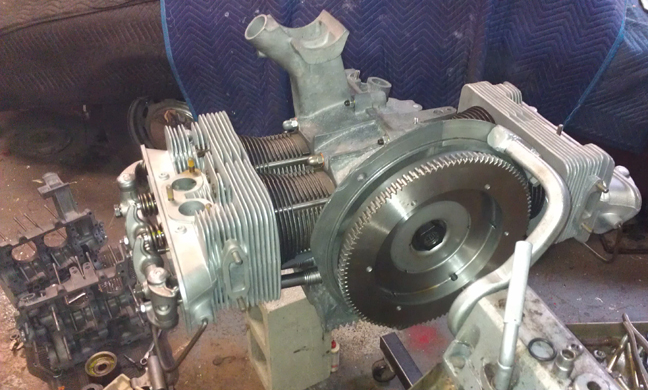
Somehow, I didn't get a photograph of the flywheel until it was already mounted! As I'd rather not take it back off just for its mug shot, I just took a shot of it mounted. What surprised me, though, was just how many attempts it took to get a good image that shows just how good this flywheel is. Most of the shots were blurry, or overly bright from reflection off of the recently refaced surfaces. Here's the image that passed muster:
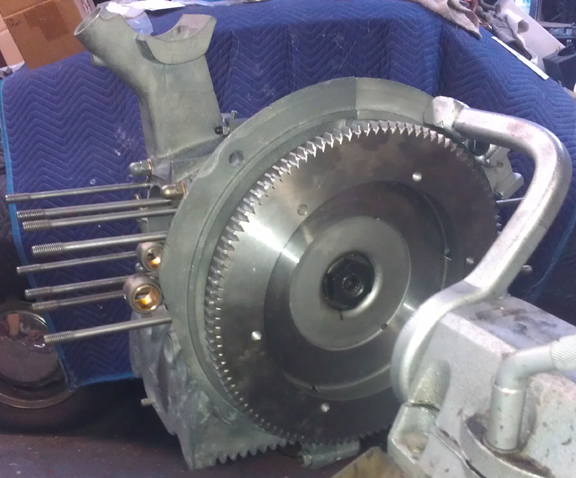
Note that while it has just been refaced, it still has plenty of bevel angle on each starter gear tooth that helps the engagement of the starter gear. These are an indicator of how much material - and therefore service life - remains. You can also see on the right side of the inner edge of the friction surface that there's some real depth to the friction face above the background surface of the flywheel. Also notable, the area surrounding the gland nut is "below" the plane of the friction face - another sign there's lots of life left in this flywheel.
 Camshaft
and Lifters
Camshaft
and LiftersAs indicated above, I got a used but wonderful camshaft from Richie Lukes some 23 years ago or so. He provided not only the camshaft, but also the matched set of lifters that had been used on that cam, marked as to their original positions. They show no wear on their cam-contact faces. Richie asked me to be sure to keep them as a set and I have.
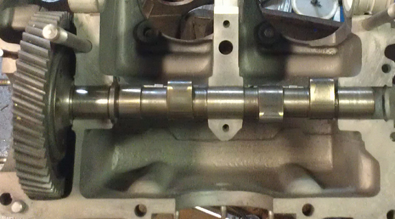
Here, I've just laid the cam in the left half to take a photo of it. I see now that the gear teeth need a little flossing! (Note also how spotless the crankcase is!)
Recall that the engine type for a '53 1500cc "normal" is 546. So, of course, that's what we see on the end of the cam... in confirmation of exactly what this cam is. And note too the perfect oil pump slot!
 As
you can see in these images, the camshaft and lifters are wonderful! The photography
was rather difficult, though, because the parts are so shiny, it's hard to get
an image that shows the face of the metal properly. One aspect of trying to
get good images that I think is interesting is how with some of these images,
my efforts to get a good clear image has resulted in magnification, so the images
here are larger than the actual parts!
As
you can see in these images, the camshaft and lifters are wonderful! The photography
was rather difficult, though, because the parts are so shiny, it's hard to get
an image that shows the face of the metal properly. One aspect of trying to
get good images that I think is interesting is how with some of these images,
my efforts to get a good clear image has resulted in magnification, so the images
here are larger than the actual parts!
If you could see them in person, you'd definetly remark on how little wear there is. Note how there is absolutely no wear on that oil pump drive gear slot!
Below, you can see how the cam followers are in great condition, as described above. I'm guessing they really didn't see service as Richie had said - they just look like they've never seen a cam lobe since they were refaced (they're clearly not new).
Crankcase preparation, described above, was a real chore. But assembly was a breeze! Here, the main bearings and cam are trial-fit.
All items are assembled into the left side (below):
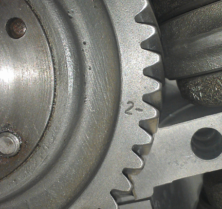 At
this point, the camshaft's mating to the crankshaft timing gear is evaluated.
The cam gear selected is about as small as it gets, at minus two (-2), and it's
worth pointing out two other things about it:
At
this point, the camshaft's mating to the crankshaft timing gear is evaluated.
The cam gear selected is about as small as it gets, at minus two (-2), and it's
worth pointing out two other things about it:
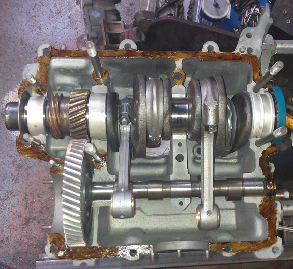 I
don't usually take a photograph showing the case sealant applied, but, for a
change, here's such an image - moments later, the right half was slid on and
a short-block was created!
I
don't usually take a photograph showing the case sealant applied, but, for a
change, here's such an image - moments later, the right half was slid on and
a short-block was created!
This seems like as good a moment as any to point out a few things visible in this image:
 Just
to be complete, here's the right half, sitting on a lidless box adjacent to
the other half on the stand.
Just
to be complete, here's the right half, sitting on a lidless box adjacent to
the other half on the stand.
Yes, the reflection of light off of some areas makes it hard to see detail. There is some sealant around every main stud / bolt - the M10s that hold the halves together, and the two M8s at bearing four.
Also note that just before putting the two halves together, the excess, which tends to pool, is wiped away.
In all my 35 years or so building these engines, I've never yet clogged an oil passage, but I sure have seen others make that mistake! The application of sealant shown here is time-proven, and in my view, the text book example of how to do it right.
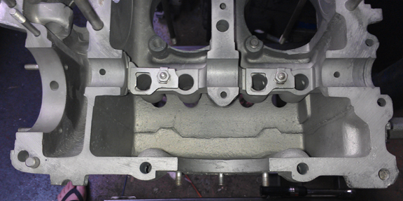
Here's the bottom bolted together, in the right image, still awaiting the parimeter bolts to be attached. Note the bright circles where the cylinders go as it shows the results of the decking operation described above.
Now the parimeter bolts - original black-zinc plated, with 14mm across-the-flats (atf), fitted with new clear-zinc plated 14mm atf nuts. You can see the bolt heads in the left half above, and the nuts in this image (below). (I would have used black zinc nuts but I ran out!)
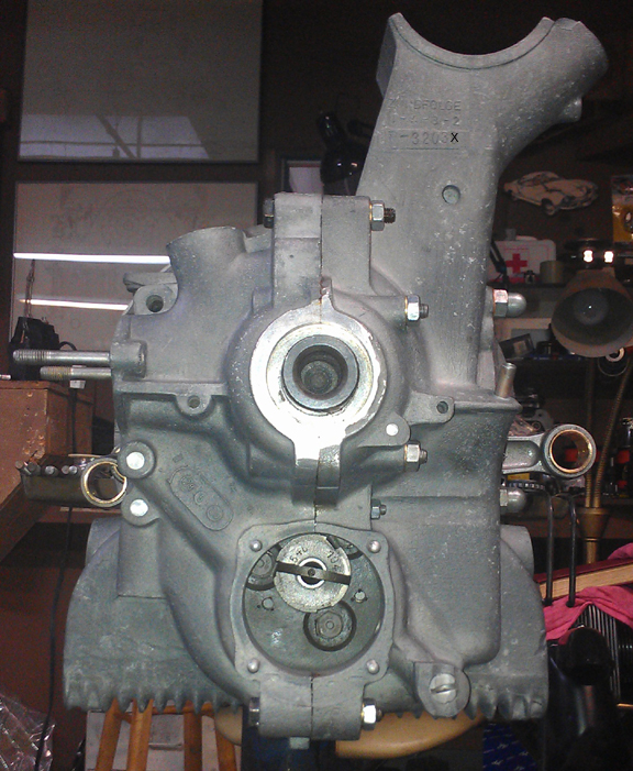
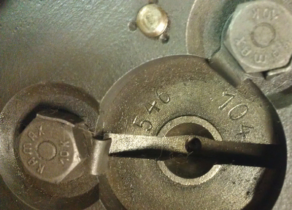
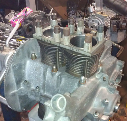
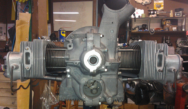
I provided this next image (at right) in this large size so you can read the cam numbers and the case number - with the last case digit illegible on purpose*.
What we have here, at right, is called a "short block," even though we don't have "blocks" for our engines - they're crankcases!
Note the head studs are still out from machining the cylinder spigots - the shiny rings of which can be seen in the two images, right / left, immediately above this one.
 Time
to install the Pistons and Cylinders.
Time
to install the Pistons and Cylinders.
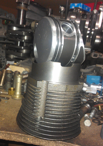
At this point, I had a decision to make as I had the following options:
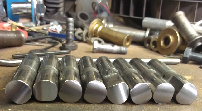
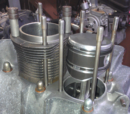
After talking with a number of people, I settled on the new set - one piston and cylinder pair is imaged at right. (However, if you prefer an alternative choice, I can accommodate that for you - lets talk about that if that's what you want.)
In my view, while the stock specification for early engines is something like 16 grams, if I recall correctly, piston weights need to match very closely in any single set, and I strive for 0.1 gram. (I could check the spec., but it's hardly worth the time: I'm matching them far closer than stock!) This set was out by only about two and a half grams - not too bad for a standard production tolerance for a cast set. (Many high-performance builders say within one gram is fine - but the closer the better.)
New parts are not exempt from careful checking!
We always check the match pistons to cylinders and match piston weights as a set, and provide any remedial action to correct any errors before installation. For example, by shuffling around the piston pins among the pistons, one can usually improve the matching of piston weights. This set naturally balanced (without removing material) to within 0.6 grams.
For many shops, from this point, installation goes very quickly, but we think this is where one needs to take one's time! The key reason one needs to take time here is that there are production tolerances on every part in an engine, and while a set of parts may look identical, there's often subtle variation between members of a set, and there are sometimes significant errors in production that weren't caught by the manufacturer's quality control processes. These errors can "stack up" and cause problems if not discovered and corrected.
 Here's
our process: Two of these steps require special tools most shops don't
have.
Here's
our process: Two of these steps require special tools most shops don't
have.
We like to carefully measure everything and then mix-and-match the parts for superior fit. We have also discovered significant manufacturing errors with this process which would likely have gone unnoticed without these measures. It is remarkably easy, for example, to overlook the circumstance of the crankshaft bore not in the true center of the crankcase, angled on the horizontal left or right of center, or not on the same horizontal plane at all. Yet examples of errors like these are not as uncommon as we would like.
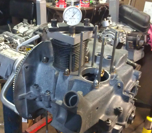
 The
height comparison check (visible above right) is done to ensure that
there are no differences between the cylinder heights that the head itself "sees."
The book value for tolerated error is 0.1mm (four thousandths of an inch), but
in this case, there was no measurable difference between one pair, and just
about exactly 0.0015" (one and a half thousandths of an inch, or 0.0275
mm) for the other. In this circumstance, that small error indicates a mismatch
in cylinder heights because we just decked the crankcase spiggots where the
cylinders seat. ...Without these special tools, and taking the time to use them,
we'd never know about such things! Most shops don't have special tools to torque
down the cylinders, so they can't do a proper check, installed, and have to
rely upon measuring the pieces lose - or risk not knowing. This is especially
important when using shims to alter / adjust the cylinder's height.
The
height comparison check (visible above right) is done to ensure that
there are no differences between the cylinder heights that the head itself "sees."
The book value for tolerated error is 0.1mm (four thousandths of an inch), but
in this case, there was no measurable difference between one pair, and just
about exactly 0.0015" (one and a half thousandths of an inch, or 0.0275
mm) for the other. In this circumstance, that small error indicates a mismatch
in cylinder heights because we just decked the crankcase spiggots where the
cylinders seat. ...Without these special tools, and taking the time to use them,
we'd never know about such things! Most shops don't have special tools to torque
down the cylinders, so they can't do a proper check, installed, and have to
rely upon measuring the pieces lose - or risk not knowing. This is especially
important when using shims to alter / adjust the cylinder's height.
By the way, it's hard to see in the image above right that the cylinders are in fact not touched on the surface that seals with the cylinder head. That may be better seen in this next image, at right: The cylinder's head sealing surface protrudes through and is not touched by the clamping tools.
 The
second special tools are used for...
The
second special tools are used for...The next thing we do is something nobody else does (that we know of) in the engine building process, and that is to measure the height the piston crown comes above the plane of the top of the cylinder. I call this the CAC, or "Crown Above Cylinder." This value is important because, firstly, it can reveal deeper problems, and because it helps us get the compression ratio equal in all four cylinders.
Here are some of the deeper problems that can be discovered through a CAC check:
In order to do this for these engines, you have to have special tools. Here, you can see them in action in the image above (right).
Even if you can't read the needle in this image, the distance between the smallest tick marks is one hundredth of a mm, or 0.0004" - LESS than half a thousandth of an inch - and you can discern to perhaps a tenth of that! So, this is a very accurate measure, performed while the cylinder is under torque, so any shims are squished flat, etc.
 The
accuracy is so good, that if you take the time to swap parts around, you can
accurately determine discrepancies in the manufacture of the various parts even
if you can't measure the parts accurately enough individually! But, we ARE splitting
hairs here! However, a benefit to both engine builder and customer is that
the ability to move parts around for better fit means that perfection is more
easily achieved, and the more equal the HP production of each cylinder, the
smoother the engine will run, the more HP the engine will produce overall, and
the longer the engine will last in service.
The
accuracy is so good, that if you take the time to swap parts around, you can
accurately determine discrepancies in the manufacture of the various parts even
if you can't measure the parts accurately enough individually! But, we ARE splitting
hairs here! However, a benefit to both engine builder and customer is that
the ability to move parts around for better fit means that perfection is more
easily achieved, and the more equal the HP production of each cylinder, the
smoother the engine will run, the more HP the engine will produce overall, and
the longer the engine will last in service.
Because this process includes the entire assembly, torqued as in service, and measures the height each piston protrudes out of its cylinder, all errors in connecting rod lengths, cylinder heights, crankcase spigots depths (cylinder bore deck), piston connecting pin heights, and shim thickness' are accounted for in the measurement results. There is no superior method.
 Cylinder
Heads
Cylinder
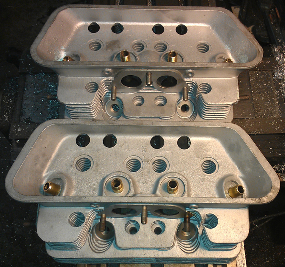
HeadsThe guides were of the 10mm variety, but there were 6 bronze seats and 2 steel seats! What's unusual about this is that ordinarily you change all the seats at one time! Someone was a bit frugal way back when!
The heads were pretty grungy, but the hot "water-based solvent" did an OK job, and then a bit of media blasting finished the cleaning, so they look like new.
They looked even better before I grabbed them with dirty hands! No worries though, they get washed a few times during the process of assembly to get rid of chips and grinding grit.
New seats were installed all around. And, while at it, all new guides were installed, too. That's very easily said, but very hard to do correctly! The reason is that the specifications book lists three different setups, and none of the parts are readily available anyway. So, you have to carefully measure what system is presently installed - and this many years on, and with clear evidence that someone had been working on these heads and did not do a complete job, you cannot trust that all the guides or seats are of the same type! The valve guides and seats had to be made for these purposes "from scratch." (Pretty useful stuff, that scratch!)
I didn't think to take any photos before working on them, so the photos begin with the guides and seats already installed. (Incidentally, I don't know what caused the distinct blue shadows in the photographs! But, I like them.)
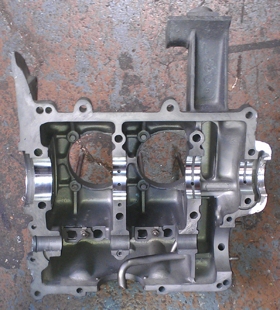
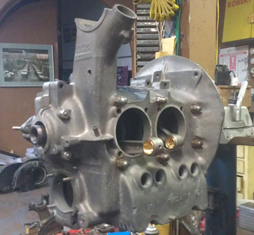
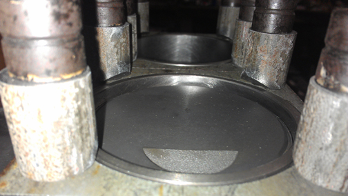
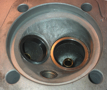
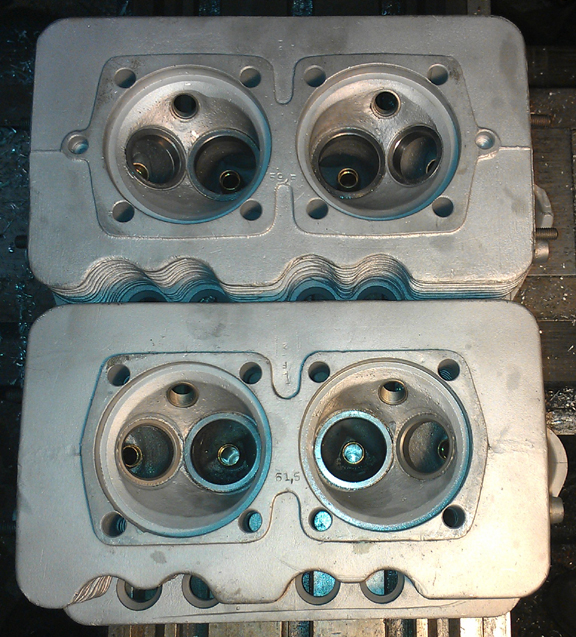 Along
the way, I figured out that the two heads are not an original pair - clearly
one of them was replaced on the engine. Which one is hard to say because they're
both early. In the image at right showing the combustion chambers, you can see
the new seats all installed - and note the two different combustion chamber
volumes; the book says they shall not be more than 1 ml different, yet these
are 2.0ml different! Note that the factory assumed you would shim all four cylinders
the same, but today we regularly shim left and right sides of an engine differently
so we don't have to take metal out when it isn't otherwise necessary! The real
point here is that these could not have been a pair from new, but, at least
they're both in great condition.
Along
the way, I figured out that the two heads are not an original pair - clearly
one of them was replaced on the engine. Which one is hard to say because they're
both early. In the image at right showing the combustion chambers, you can see
the new seats all installed - and note the two different combustion chamber
volumes; the book says they shall not be more than 1 ml different, yet these
are 2.0ml different! Note that the factory assumed you would shim all four cylinders
the same, but today we regularly shim left and right sides of an engine differently
so we don't have to take metal out when it isn't otherwise necessary! The real
point here is that these could not have been a pair from new, but, at least
they're both in great condition.
Not shown here, the heads were both later decked and fly-cut because to install seats, the heads have to be heated pretty high, but cannot be supported during that period and they can warp slightly. Decking ensures the cylinders are in the same plane. Then, the surface closest the crankcase gets cut down to match however much was taken out in cleaning up the cylinder sealing surface, thus ensuring the heads don't foul on the cylinder's top fin.
Normally I don't take the time to show such things, but every piece here had to be made just for these heads, so I thought I'd show off what a great job was done in making the seats. Please note in the image below just how perfectly the seats fit, both intake and exhaust, regarding matching the inside diameter on the bottom side of the seat, and in matching the height exactly. They're also centered perfectly - as centered as Porsche did originally!
The valves were all cleaned, refaced and polished. And of course, the valve seats were ground (after the above photos were taken).
It was decided to use single springs instead of the original dual-springs, as provided for by Porsche - the so-called "third version". Someone said as recently as December 17, 2012, that RIMCO did their two piece case heads recently, so I called them to see if they had any more two-piece-case valve springs. They said they did! However, when I started prattling off dimensions, the fellow stopped me and said that no, based on the measurements I gave him, these are NOT the correct springs! (Just as I suspected. By the way, the correct dimension data is in the little specifications book, version three.) BE CAREFUL what you buy! Lots of people think Two Piece Case valve springs are the same as the younger engines, but they are not!
Of course, not just the spring, but the installation is vital. Just as with other engines I build, the springs are shimmed where the valve and retainer are position specific, and where the strongest springs (there is always some varriation) get the heavier (intake) valves. This is done so that all the valves float at the same time and thereby give a good signal to the driver to back off!
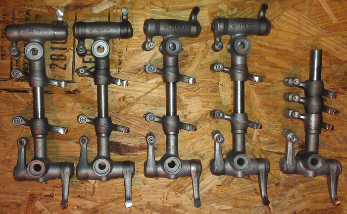
The rocker gear was all thoroughly cleaned and the contact surfaces refaced. Here you can see the latest batch of them done and ready for installation - and a few spare bits, too! (I have extra bits for barter.)
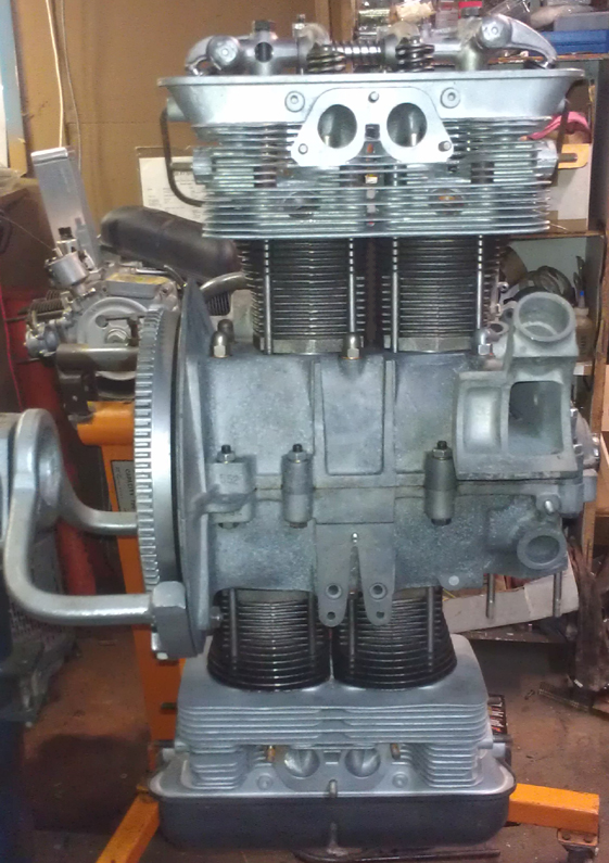
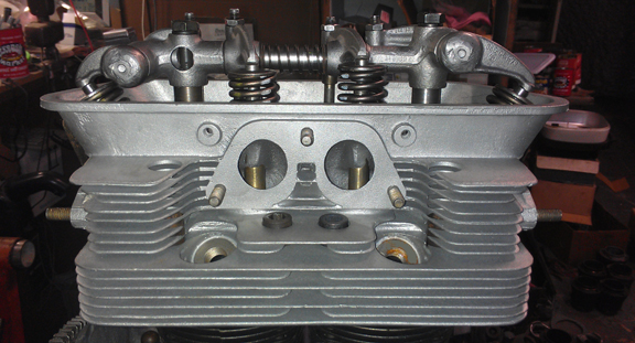
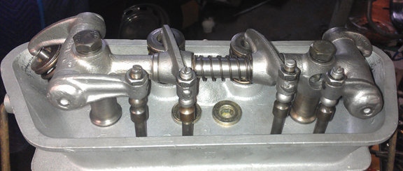
Now, we mount the heads and then the rocker gear...
Yes, on the left side in the image above, that's another two-piece Porsche engine that's following along behind this one! Look here for the ad / web page describing that one!
OK, time now to do a little more on the crankcase...
Oil pump, sump screen and cover, oil control piston - only took a few minutes.
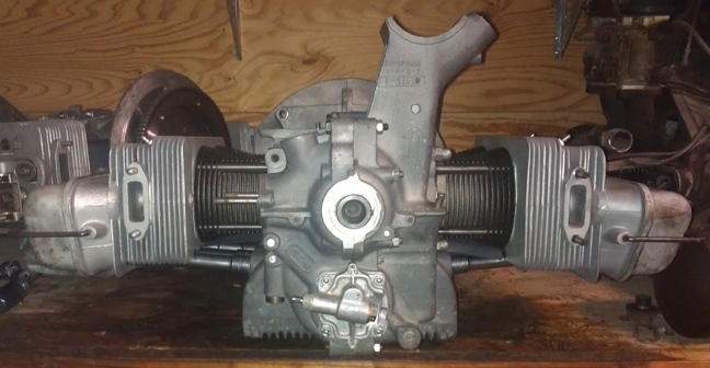
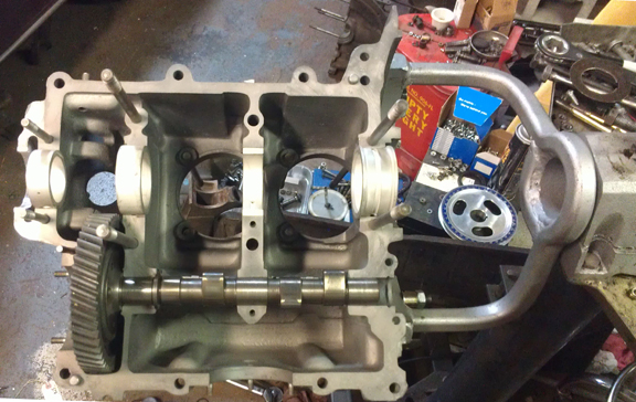
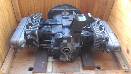
Here it is as a longblock, minutes away from being ready for pickup or delivery - yeah, those are the wrong valve covers - will replace them when the paint dries on the right ones! Oops - decided NOT to paint the originals because I'm concerned that during preparations for painting that I risk getting sandblasting media into the vents that I can't get out.

Yes, the distributor drive shaft has not been installed because it should be left out until a distributor will be installed. Otherwise, if anyone rotates the engine backwards, the drive gear will ride up on the bronze crankshaft gear and may damage it....
Well, off it goes to its new home. I had originally provided a crate thinking it would be going on a sea voyage, but the new owner decided to have it sent as air-cargo to the EU. That required a crate using no "solid wood." So, I had to re-crate the engine!
In the following images, the crate construction is shown, which may be of some interest to folks, and then loading it up for its trip to SFO (the airport of San Francisco) for loading into an aircraft, then on to Europe.
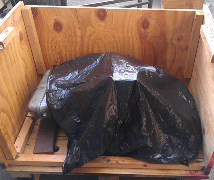
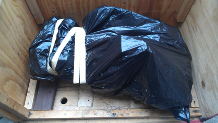
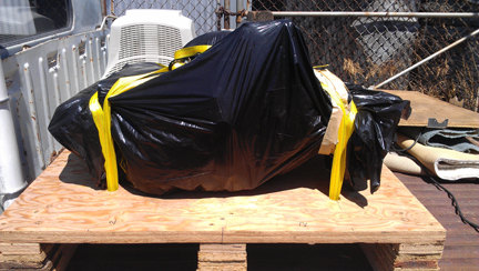
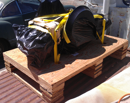
Before crating, but after dismounting from the engine stand, I torqued the flywheel a second time to ensure it's on good and tight. Then, I taped off all openings and brought the engine to the crating area using the over-size floor jack, whereupon I sprayed the engine liberally with WD-40 in preparation for what I thought was going to be a sea voyage. I then bagged the engine as I have several others in the past.
First, position to lock it down in the crate with wooden blocks, one of which is drilled for the right hand stud - it won't lift out!
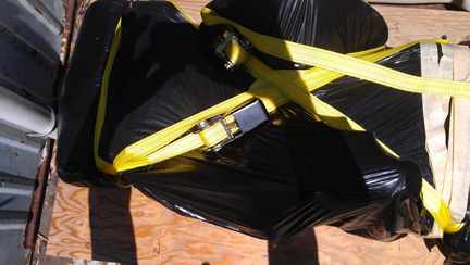
Bag it - right side first:
Tape the bag down:
Now the left side:
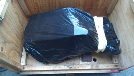
Then screw the wooden plate down on the right side, slide the engine to the right and thereby lock the engine to the floor, then screw down the block on the left that keeps it from shifting left, and then strap the engine down, first one side, then the other. Each strap is rated at 1500 lbs.
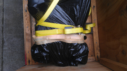
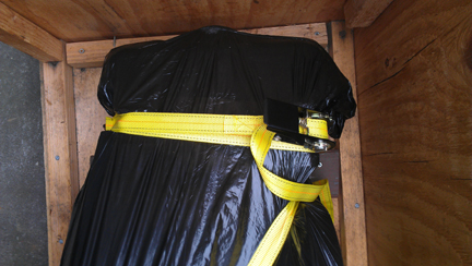
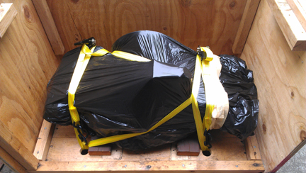
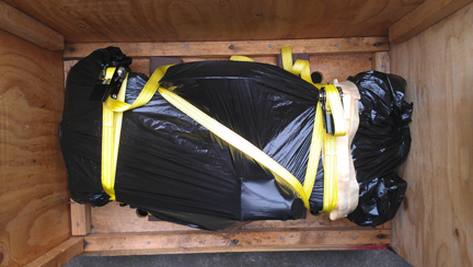
Done! (Or... so I thought!)
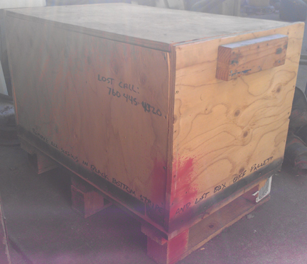
OK, now, introduce the EU-safe crate! NO SOLID WOOD. That means a nearly whole new crate - bottom has to go! Wood joining strips for sides and top, have to go, too... AND, the runners on the bottom!
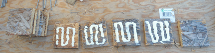
So, I secured a 1" thick sheet of plywood and made a new base. First, I took some OSB (oriented strand board - a plywood-like product) and cut a whole bunch of 4" squares, glued them, stacked them on top of each other and screwed them together to make 6 four inch cubes:
I then cut 6 four inch wide strips of the one inch plywood and sandwitched the just made cubes, gluing and screwing it all together into three runners, and then I screwed these to the 1" thick plywood base I'd cut out:
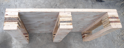
Now, there's something to put an engine on!
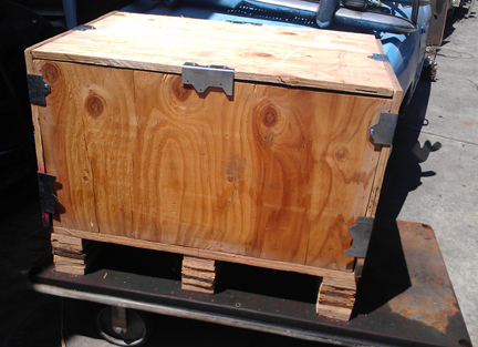
I secured some metal brackets - Simpson Strong-Tie brand - to attach the sides and lid. Here, I mocked it up and decided where the brackets go:
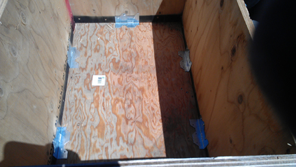
The inside:
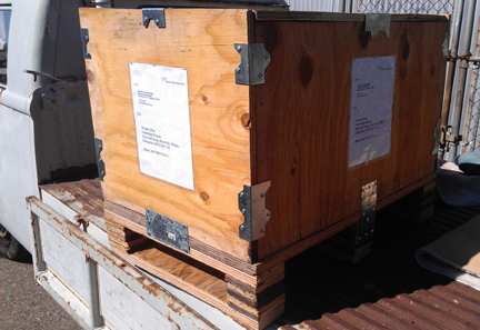
Now, to avoid loading troubles, the intermediate shipper who was running this over from Oakland to the San Francisco airport (SFO) brought his vehicle and set it in the parking area - a drop-gate VW double-cab, by the way. With the crate's base set on the back bed, we then set the engine on the base, and I strapped it in much as before. (Note that either strap could hold the engine down without the other - redundancy is just for safety.)
Then, install the sides, and added four flat plates to help tie the sides down to the base very securely and help tie in all three runners for additional strength and safety - left the top off until the very end, so in the upper of the two images below, it's still lose:
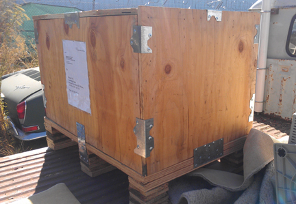
...This, (and some paperwork!) and it's on its way to Europe via air-freight!...
NOTE: If this engine is sold as a long-block... One should NOT install the distributor drive gear without also installing a distributor because if anyone rotates the engine backwards, it will push the drive gear up where it can damage the bronze drive gear! Therefore, the distributor drive is NOT mounted until the last reasonable moment!
When you're ready for work on your machine, just let us know.
Because some people are keeping logs of VIN and engine numbers and then purport to tell people what someone else has, out of respect and concern for a buyer's privacy, exact VIN and engine number data are not published here.