Copyright © 2007 - 2025, Coachworks For contact data Click Here.
Copyright © 2007 - 2025
Copyright © 2007 - 2025,
Coachworks For contact data
Click Here.
![]()
 Porsche
Engine:
Porsche
Engine:This engine has been sold, however, we nearly always can build one of these on fairly short notice, so please contact us.
This 1965 356 SC engine came to us as a "core" and we have just performed on it a complete overhaul, fully balanced for smooth running, long life, and a few more HP.
The rebuild was performed to the same exacting standards we've become known for with new parts sprinked throughout and keen attention to detail. Some rebuild highlights:
Again, this is an incomplete summary; the text and images below describes the rebuild process in detail. Every detail about the engine has been attended to; nothing was ignored.
Of course this engine has the late-type oil pump, late rockers, etc. During this rebuild it was fitted with high-compression, biral 86mm pistons and cylinders.
I received this engine from a customer who purchased another engine from me. Some time after that transaction he said he was pleased with his experience with me, trusted me, and asked if I would please receive this engine from a non-reputable builder. He explained he had purchased this engine from that party expecting some very specific details, but had since come to perceive he "had been taken." So, I was contracted to do an investigation into this engine. Unfortunately, the investigation proved his basic hunch correct: there were many assembly errors, the engine was not as my customer had said it was represented to him, and, worst of all, the engine needed to be gone through "from top to bottom." Unfortunately, nothing further about this engine is known to us.
This engine has the type number 616/16 (SC) stamped into the main half pairs, but came to me with a replacement timing cover into which someone had stamped the engine numbers cited (81696x*). However, that cover, which was clearly an un-numbered, new replacement part prior to having been installed, was of a 912 type. The factory itself provided 912 timing covers as replacement parts on 356 engines, however this effort while clearly not done by Porsche, wasn't too bad. And, having on hand a genuine 356 replacement cover from the 912 era, I did a little machine work to improve it a bit and it's now quite passable as if original. ...Presumably, the numbers stamped into this timing cover were from a former owner's original engine.
As described in the background section, the reason I received this engine from my customer was because they didn't trust the previous (just completed) rebuild. My customer paid me to disassemble and inspect the engine, and prepare an analysis which they might then use against the individual who sold it to them in support of their claim of fraud. Thus, my role was one of "expert witness." Because a case against the party that rebuilt this engine may yet be pending, it is inappropriate for me to get deep into details about the teardown.
Given the circumstances, I trust that it's understandable that while I may here and there share a bit more about what I found in this engine when I got it, and what I did about it, my focus in this document is on the rebuild effort. If you want to know more, please ask privately.
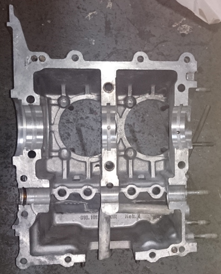
This crankcase cleaned up nicely and didn't need an align-bore. It looked so good, at first I thought it was a recent align-bore but no, it just never had a lot of service on it.
The timing cover is imaged down below, just before it was installed.
 The
crankshaft that came with the core was the same one that went back in: a new,
modern replacement with almost zero running time. (It was pretty easy to tell
that the former "rebuild" had never been put into service but had
been test run briefly.)
The
crankshaft that came with the core was the same one that went back in: a new,
modern replacement with almost zero running time. (It was pretty easy to tell
that the former "rebuild" had never been put into service but had
been test run briefly.)
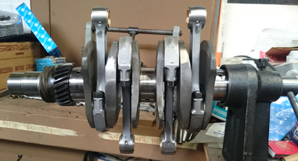
The crank didn't have any manufacturer's markings, and with unknown origins, I had it rotationally balanced - you can see the bright spots in a few places in the image at right; that's where material was taken off to effect the balancing.
As usual, when it was ready I mounted the crankshaft up on the ole crankshaft stand and mounted up the rods.
I usually take images of the rods by themselves, but on this occasion, I can't find the photos. (I got a new camera (phone!) at the time this was going together, so they may be on the old phone...) However, there's little need: In the image at right you can see that they're the late type by the way the rod caps protrude beyond the crankshaft, and how relatively "square" the rod bottoms are. And, you can see that the bushings are new, and that the rods have been balanced (bright spots on the little-ends are the give-away).
 Lacking
an image of this set other than on the crank (above right), I offer you an image
of a batch I did a year ago or so (below right). I rebuild rods in batches -
it's easier / faster / cheaper that way as it keeps setup time to a minimum.
Lacking
an image of this set other than on the crank (above right), I offer you an image
of a batch I did a year ago or so (below right). I rebuild rods in batches -
it's easier / faster / cheaper that way as it keeps setup time to a minimum.
For me, "rebuilding the rods" means to:
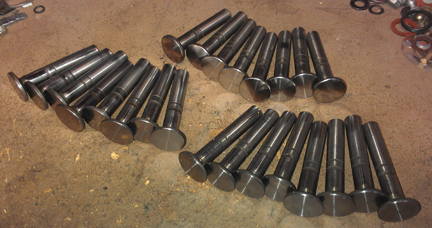
 AT
RIGHT: This is all standard work so I seldom take photos of them in-process,
however, here's an image of a set being balanced - this is actually the
very next set I did, for the next engine after this one.
AT
RIGHT: This is all standard work so I seldom take photos of them in-process,
however, here's an image of a set being balanced - this is actually the
very next set I did, for the next engine after this one.
The big end of the rod is placed, tab-end down, on the ball mounted to the stand at left of the scale while the little end goes on the ball mounted in the rock-able fixture that's sitting on the scale.
The set at right, next to the scale, will be used in a future engine, but they're also the late type, as can be seen by the rod caps.
 Crankcase
Assembly
Crankcase
AssemblyAs for selection of a good cam, I turned to my good friend Demetri Elgin who supplied me with a new example of his MFT6708, which he describes as a stock grind in terms of timing but with a bit higher lift for a little more power, but not so much that you have to either worry about coil-bind or too-high "ramp speeds" which can induce valve float. In short, instead of holding the valve open at a particular spot, it keeps going up until it starts coming down again - less of a pause at the open point. This cam should give the same great low-end performance, coming in at 2000 RPM, and continue to give good power through to 6000, just like the stock cam provides, with maybe a little more power in the middle.
Also worth pointing out here that I always reface the cam followers, just to be sure they wear-in correctly, though it was probably unnecessary in this instance.
 Select
a camshaft, plop in some new main bearings, set the crank in and you're good
to go, right?
Select
a camshaft, plop in some new main bearings, set the crank in and you're good
to go, right?
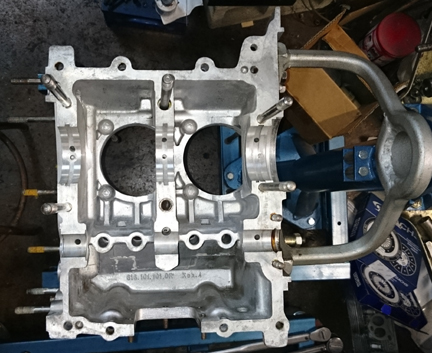
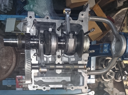
AT RIGHT: This engine is almost ready for the other half to be installed! Things were paused here to select the right sized gear.
Well, not so fast! The gear on the end of the camshaft is vital. One of the problems with the previous rebuild was that the cam gear was too tight. So, I had to select another one.
Sounds easy, right? Well, it so happens that nearly every engine needs a "negatively sized" gear. I don't know why they nearly all seem to need smaller gears, but I can't recall ever recall, not even once, needing to install a "plus-sized" camshaft gear! And, I've been doing this since the late 1970s! So, even the most well-stocked workshop will run lean on smaller-diameter gears.
And that's why we chose to find a gear manufacturer and take some new gear castings and make some smaller diameter ones!
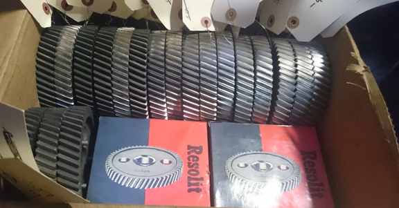 We
just happened to have a stash of new cam gear castings - doesn't everybody have
a big box ful?! - and our gear manufacturing vendor cut gears to our size specifications.
We had them start at the "zero sized" gear and give us a gear cut
to a "pitch diameter" in increasing steps yielding a thousandth of
an inch increase in lash (clearance) between gears. This pretty well guarantees
there's a perfict fit in there somehwere!
We
just happened to have a stash of new cam gear castings - doesn't everybody have
a big box ful?! - and our gear manufacturing vendor cut gears to our size specifications.
We had them start at the "zero sized" gear and give us a gear cut
to a "pitch diameter" in increasing steps yielding a thousandth of
an inch increase in lash (clearance) between gears. This pretty well guarantees
there's a perfict fit in there somehwere!
AT RIGHT: A couple of dozen cam gears, accurately sized, ready to go at the drop of a hat!
This engine required ALMOST the smallest gear that we had made! I was astonished it needed one so small and wonder if there was something about how the previous "mechanic" had mounted the gear onto the crank. . . But I wasn't so curious as to take the gears off to find out!
Before leaving the subject of camshafts entirely, note that Elgin provides cams that are parkerized. YOU DO NOT NEED TO RUN THE ENGIN HARD to "run-in" a parkerized camshaft! This is such an important point because I regularly hear people told by their cam grinders that they need to do this. So, we offer you here a little bit of clear thinking about this issue:
Parkerizing is a hardening process which eliminates any "need" to over-rev the engine to work-harden the cam lobes. (If anyone ever tells you you must rev your freshly rebuilt engine to high-rpm in order to work-harden the camshaft lobes, you've chosen the wrong parts vendor / cam grinder! This should never be required! If you're racing, that's one thing, but most of us can afford the normal, gentle run-in process that results in a long-lived engine...)
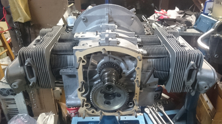
 OK,
wtih all that behind us, moving on (!!) ... Here's the crankcase being buttoned
up. Notice the blue on part of the cam gear - this is "machinists' dye"
used by the gear manufacturer in cutting and sizing the gears.
OK,
wtih all that behind us, moving on (!!) ... Here's the crankcase being buttoned
up. Notice the blue on part of the cam gear - this is "machinists' dye"
used by the gear manufacturer in cutting and sizing the gears.
I don't recall why at the moment but the timing cover was not installed at this time. I recall that maybe it was because the nose bearing (main bearing #4) hadn't been installed yet.
As it was, the assembly proceeded on.
 Cylinder
Heads
Cylinder
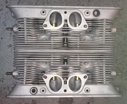
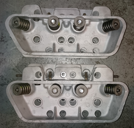
HeadsThe heads are the early 912 type (not the black anodized process used on production SC and S90 heads but identical to SC heads in port and combustion chamber sizes) and looked really great, and are effectively perfect.
However, all heads get the usual treatment no matter what they look like! They're carefully cleaned and examined for cracks. New guides are installed and valve seats reground. Valve seats are replaced when they've been ground too far, and if any decking / re-surfacing is required on any machined surface, that's done too. All threads / studs are checked and any flaws remedied. On 912 type heads, new rubber grommets are used at the vent ports.
These heads have never been cracked, there are no broken fins, and didn't need new seats or fly-cutting.
Fitted to these heads are great valves. They're originals, not aftermarket replacement which are all you can get new today. Further, and vitally, the exhaust valves ARE the sodium filled type, which haven't been available new for some years now. Of course, the valves have been checked for length (stretching makes them unworthy), polished, and refaced, so they're effectively perfect too.
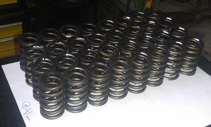 New
springs, of course, are carefully selected. Experience has shown that the stock
spring pressures are a bit too weak and it's possible to over-rev and have a
valve struck by a piston. So, in the modern era (for many decades now), we run
tougher springs. 80 lbs "on the seat" is a minimum, but I like to
run them in the 90+ pound range, of which this set is an example. A big batch
of valve springs (typically 40 at a time) is sorted into matched spring tension
sets where they may differ only by a pound or two, very much more descriminating
than the factory specifications allow. This is because it's very important that
all the valves float at the exact same time, so that the driver KNOWS they're
flogging it a bit too hard and can back off. In contrast, if one valve is floating,
the driver will likely not realize it and damage can occur.
New
springs, of course, are carefully selected. Experience has shown that the stock
spring pressures are a bit too weak and it's possible to over-rev and have a
valve struck by a piston. So, in the modern era (for many decades now), we run
tougher springs. 80 lbs "on the seat" is a minimum, but I like to
run them in the 90+ pound range, of which this set is an example. A big batch
of valve springs (typically 40 at a time) is sorted into matched spring tension
sets where they may differ only by a pound or two, very much more descriminating
than the factory specifications allow. This is because it's very important that
all the valves float at the exact same time, so that the driver KNOWS they're
flogging it a bit too hard and can back off. In contrast, if one valve is floating,
the driver will likely not realize it and damage can occur.
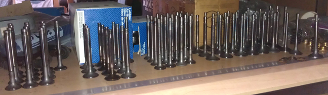 AT
RIGHT: All valves are checked for wear, being bent, and their heights (lengths)
are checked for stretching. The good ones are re-faced, and stems polished.
Here they await selection for an engine.
AT
RIGHT: All valves are checked for wear, being bent, and their heights (lengths)
are checked for stretching. The good ones are re-faced, and stems polished.
Here they await selection for an engine.
With springs selected, the valves are then carefully assembled into the heads. The springs are then carefully shimmed such that each valve, its bore and its retainers and keepers are kept position specific through the process to ensure consistency.
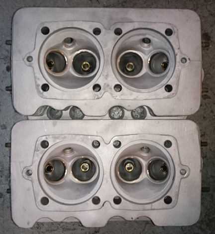
After the valves are fitted, the combustion chambers are measured with a burrette. Both heads work out to about 63 ml - a bit on the large side - which is further supporting evidence that these heads are of low mileage.
 Pistons
and Cylinders
Pistons
and CylindersIncorrect pistons and cylinders had formerly been fitted to the engine - though perfectly useable modern "big-bore NPR copies" (iron cylinders in 86mm bore). However, these days there are quality sets of "big-bore SC / 912 copies", which I selected instead - new of course.
They're 86mm. They're biral cylinders. They're beautiful.
Original SC (and 912) cylinders are "biral." Biral cylinders are great because they have aluminum fins - with great thermal conductivity and emissivity - combined with the durability of an iron liner. However, the casting of the fins on the iron liner does aneal the iron, so they have a somewhat shorter lifespan, which is why finding a runable used set today is exceptionally rare.
That's where these new pistons and cylinders come in; they're Just Like Stock! ...Except for the bore, that is. (These are 86mm while the stock bore is 82.5mm.) Another great thing about these Ps&Cs is that the pistons are high-compression, just like the original SCs were! (We're talking 9.5:1 here.)
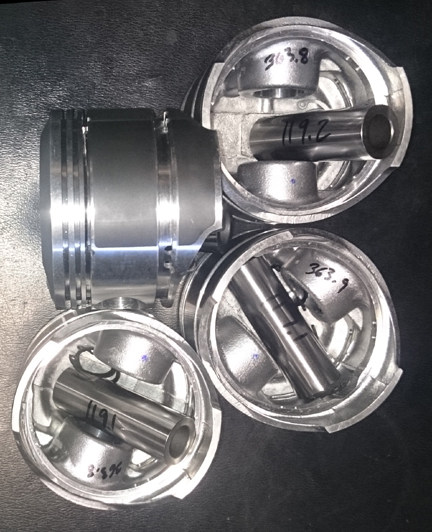
New parts are not exempt from careful checking!
We always check the match pistons to cylinders and match piston weights as a set, and provide any remedial action to correct any errors before installation. For example, by shuffling around the piston pins among the pistons, one can usually improve the matching of piston weights. This set naturally balanced (without removing material) to within 0.1 grams - the official specification is ten grams (10g) - with three of them at the exact same weight (483.0g) and one 0.1g lighter. You can't really ask for it any better than that!
We also always check ring gaps, even on new sets.
We then turn our attention to the cylinders! Is their bore consistent, properly honed? What about their heights?
AT RIGHT: Here we see the height being measured. It may be hard to tell but the cylinder and the measurement stand are situated on a sheet of thick glass, so it's a flat surface. To our great surprise, this set had ONE cylinder a bit taller than the others, which were identical.
The solution to this was to mount the cylinder in the lathe and trim it a bit!
For many shops, from this point, installation goes very quickly, but we think this is where one needs to take one's time! The key reason one needs to take time here is that there are production tolerances on every part in an engine, and while a set of parts may look identical, there's often subtle variation between members of a set, and there are sometimes significant errors in production that weren't caught by the manufacturer's quality control processes. These errors can "stack up" and cause problems if not discovered and corrected.
Here's our process: Two of these steps require special tools most shops don't have.
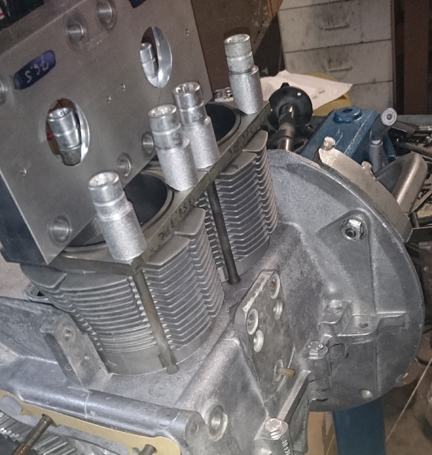 Install
cylinders with estimated shimming (with no rings, this goes quickly) and torque
down with special tools for two purposes:
Install
cylinders with estimated shimming (with no rings, this goes quickly) and torque
down with special tools for two purposes:
AT RIGHT: Here, thick metal plates retain the cylinders torqued to the case - so any shims are squished flat! - and the relative hights of the two cylinders are compared. The heavy aluminum block provides a nice flat surface from which to measure any discrepancy in height by use of a feeler gauge. The factory tolerance for error here is 0.1 mm (0.004").
We like to carefully measure everything and then mix-and-match the parts for superior fit. We have also discovered significant manufacturing errors with this process which would likely have gone unnoticed without these measures. It is remarkably easy, for example, to overlook the circumstance of the crankshaft bore not in the true center of the crankcase, angled on the horizontal left or right of center, or not on the same horizontal plane at all. Yet examples of errors like these are not as uncommon as we would like.
Here (above right) you can see them being fitted for height comparison check - this is done to ensure that there are no difference between the cylinder heights that the head itself "sees." The book value for tolerated error is 0.1mm (four thousandths of an inch), but in this case, following the trimming of one cylinder as cited above, there was no measurable difference between one pair, and less than 0.0015" (less than one point five thousandths of an inch, or 0.0275 mm) for the other.
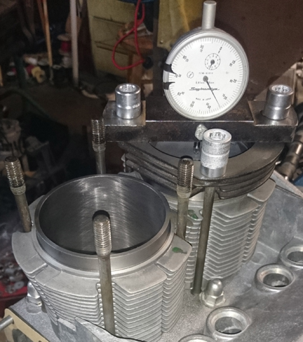
The next thing we do is something nobody else does (that we know of) in the engine building process, and that is to measure the height the piston crown comes above the plane of the top of the cylinder. I call this the CAC, or "Crown Above Cylinder." This value is important because, firstly, it can reveal deeper problems, and because it helps us get the compression ratio equal in all four cylinders.
Here are some of the deeper problems that can be discovered through a CAC check:
In order to do this for these engines, you have to have special tools. Here, you can see them in action on this engine in the two images above right.
Even if you can't read the needle in these images, the distance between the smallest tick marks is one hundredth of a mm, or 0.0004", and you can discern to perhaps a tenth of that! So, this is a very accurate measure, performed while the cylinder is under torque, so any shims are squished flat, etc.
The accuracy is so good, that if you take the time to swap parts around, you can accurately determine discrepancies in the manufacture of the various parts! But, we ARE splitting hairs here! However, a benefit to both engine builder and customer is that the ability to move parts around for better fit means that perfection is more easily achieved, and the more equal the HP production of each cylinder, the smoother the engine will run, and the more HP the engine will produce overall.
AT RIGHT: All the checking is now done so the rings are fitted and the pistons hung in anticipation of the cylinders being mounted up. The CAC data and combustion chamber volume data is compared, head placement (right vs left) decided, and shimming selected.
Because this process includes the entire assembly, torqued as in service, and measures the height each piston protrudes out of its cylinder, all errors in connecting rod lengths, cylinder heights, crankcase spigots depths (cylinder bore deck), piston connecting pin heights, and shim thickness' are accounted for in the measurement results. There is no superior method.
 Final
Assembly
Final
AssemblyAt this point the engine is ready for its cylinders to be slipped on and then cylinder heads fitted.
Prepare the head "bolts" and washers, prepare the pushrod tubes, prepare the lower cylinder air deflection plates and their wire retainers, and get the torque wrenches set, and bolt on those heads!
My pattern is to mount one head, torque it to 7 ft lbs, then mount the other head the same way, and then alternate between the heads with an ever-increasing torque up to the final torque value, then repeat the final value until the fasteners no longer turn when torque is applied.
 OK,
mount the valve gear, adjust the valves and pop on the valve covers.
OK,
mount the valve gear, adjust the valves and pop on the valve covers.
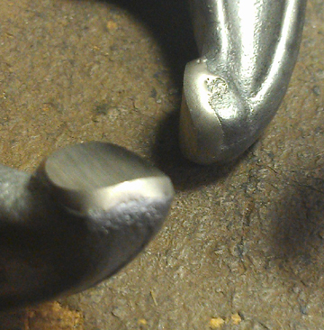
As mentioned elsewhere, the rockers are succeptible to wear at the contact face with the valve. This area was surface hardened by Porsche. When that surface is worn through, rapid wear proceeds. This makes it very difficult to adjust the valves.
AT RIGHT: A pair of rocker arm tips showing the hard facing applied. The rockers in the image are a representative sample, not the actual ones in this engine.
As a reliable solution to this problem, we "hard face" all rockers. In this process a hard alloy metal is welded to the tip of each rocker and then the rocker is refaced. The result is a surface that won't wear through very quickly! And thus, many enjoyable, reliable miles result.
AT RIGHT: The timing cover ready for installation - note how clean it is inside!
Oh, and because we didn't get it done earlier, the timing cover needs to be installed, and this work went very quickly - as it should! - as all the prep work was already done.
And yeah, I replated the oil control piston's bypass tube that relieves pressure from the underside of the oil control piston so it can function properly. . . Why plate this? Why not?
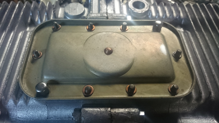 Then
fit the oil drain plug, and sump screen and plate. Of some small note is that
all the sump studs are original and in fine condition. I used new cap-nuts to
protect the studs into the future. (Of small note, these cap nuts are from VW
and are just a little too short, but I found deeper cap nuts that fit these
longer studs.)
Then
fit the oil drain plug, and sump screen and plate. Of some small note is that
all the sump studs are original and in fine condition. I used new cap-nuts to
protect the studs into the future. (Of small note, these cap nuts are from VW
and are just a little too short, but I found deeper cap nuts that fit these
longer studs.)
AT RIGHT: This may be the most beautiful original sump plate I've ever seen! The bright spot on the right hand side is just a reflection of light - there's no blemish there!
Then, fit the two oil control pistons.
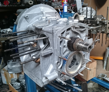
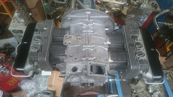 And
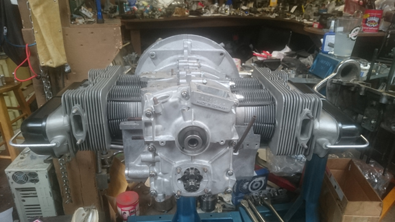
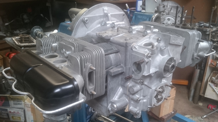
now here it is as the longblock, (almost) ready for pickup or delivery!
And
now here it is as the longblock, (almost) ready for pickup or delivery!
AT RIGHT: Virtually all done! Just needs the flywheel mounted, end-play set (see below).
Can't forget the oil pump! In the image below, the cover for it is still in the parts washer - it should be gleaming just as much as the rest of the engine! However, I have modified the timing cover to accept the full-flow system from Precision Matters. If you know where to look and what to look for, you can see the tiny notch cut into the pump area to accept the full-flow system.
 While
the end play can be set and flywheel mounted while the engine is up on the stand,
I prefer to do it when the engine is a lot closer to the ground! So, after all
the stand-work was done, the engine was dismounted and the flywheel work accomplished.
While
the end play can be set and flywheel mounted while the engine is up on the stand,
I prefer to do it when the engine is a lot closer to the ground! So, after all
the stand-work was done, the engine was dismounted and the flywheel work accomplished.
All new parts: New gland-nut, flywheel, pressure plate and clutch disk.
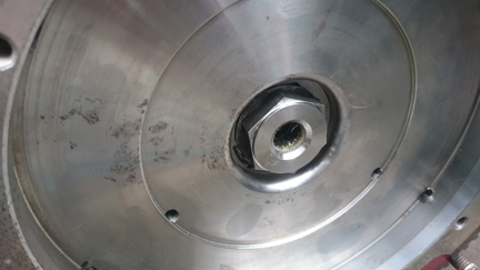
ABOVE LEFT: An old gland-nut was used for the process of setting the end-play because it requires installation and removal repeatedly. The new gland-nut was only fitted after the flywheel end-play was set. It's at 0.11mm - just over 4 thousandths of an inch.
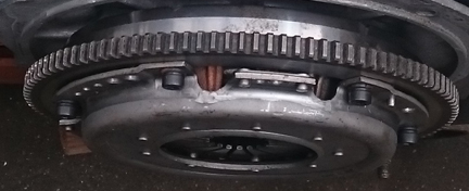
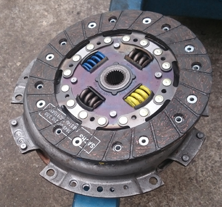
ABOVE LEFT AND AT RIGHT: The markings aren't visible, but the flywheel was balanced separately, and then balanced with the new pressure plate seen at right. You can see the dowel pins that locate the orientation of the pressure plate in the assembly. And you can see the new socket-head cap screws used to retain the pressure plate - the stock method - and yes, those are grade 10.9 bolts. Also, the large springs of the late pressure plate are also interesting - why the different colors? Curious!
NOTE: If this engine is sold as a long-block... One should NOT install the distributor drive gear without also installing a distributor because if anyone rotates the engine backwards, it will push the drive gear up where it can damage the bronze drive gear! Therefore, the distributor drive is NOT mounted until the last reasonable moment!
Because some people are keeping logs of VIN and engine numbers and then purport to tell people what someone else has, out of respect and concern for a buyer's privacy, exact VIN and engine number data are not published here.