 ©
Copyright 2016 - 2021, Coachworks ©
Copyright 2016 - 2021, Coachworks
©
Copyright 2016 - 2021, Coachworks ©
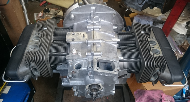
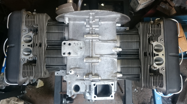
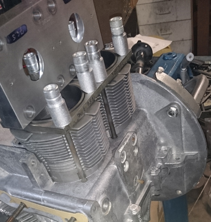
Copyright 2016 - 2021, Coachworks AT RIGHT: Yes, those are the factory-blackened SC heads mounted on modern big-bore biral cylinders!
This 1963 356 SC engine came to me as a "core" and has just undergone a complete overhaul, and is fully balanced for smooth running, long life, and a few more HP.
This engine is being prepared in long-block form, with a few extra goodies, but may be purchased complete, ready to install, with only a few days delay. This engine may optionally, on customer request, be delivered "run-in" as per Porsche factory specifications as outlined in the Workshop Manual, operations 52 EN, 53 EN, and 54 EN, pages E83 and E84.
SPECIAL NOTICE
This web page is still under construction! This disclaimer will be removed when all the images and text work has been completed.
Meanwhile, the contents are reasonabley accurate, just incomplete.
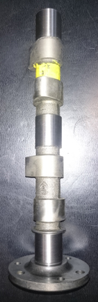
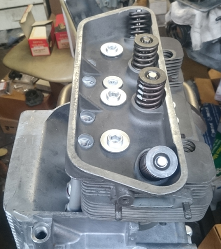
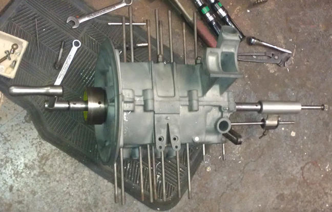
AT RIGHT: The lighting makes the cylinder heads look a bit pale, but they're genuine SC, and are seen a bit better below. Note the notch in the oil pump just to the left of the gears: That's for the optional Precision Matters full-flow system.
This engine has genuine SC case, heads, and crankshaft (not 912), all in great condition. New, modern "big-bore SC" pistons and biral cylinders were fitted - iron cylinders with cast aluminum fins fitted with 9.5:1 compression ratio (nominal) as original, but with a larger bore of 86mm, making 1719cc. The crankcase was alignbored to 1st over during this renovation. A brand new, wide-lobe factory replacement cam, the so-called "Ro-200" was fitted. As with all engines we build, all new valve guides and springs were fitted, the rockers "hard-faced", and all the other high-quality details were applied as outlined in this document.
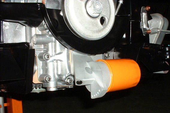
Of course this engine has the late-type oil pump, but in due consideration for better oil filtration, a notch was machined into the pump's outlet that permits the optional fitting of the Precision Matters brand full-flow oil system (as seen here) without further modification - we run these units on ALL our own engines! If not used, there's no effect, visual or mechanical on the engine, but if desired, this full-flow oil system can be added with the engine still installed in the car and fully assembled!
This engine has undergone a thorough rebuild as described herein. Every detail about the engine has been attended to; nothing was ignored.
This engine came from a very early SC coupe which lived its life in and around Davis CA, but had sat since the late 1980s or early 1990s.
Unfortunately, it was coated in leaf-litter and debris from sitting outside for so long!
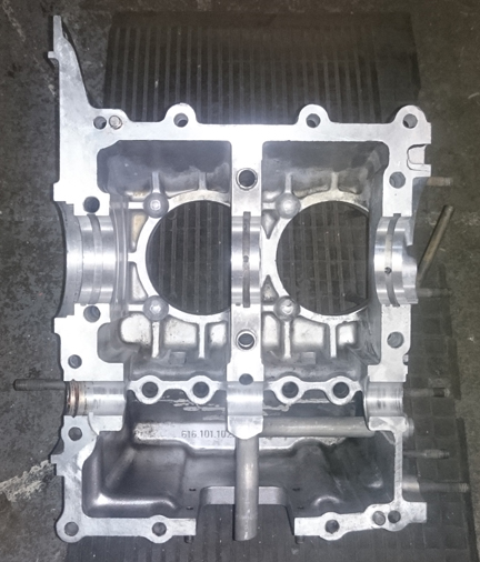
This crankcase is in great condition! It needed a good cleaning, and it was really dirty. Thankfully, it wasn't corroded...
Cleaning was the typical chore due to the fact we can't use solvents for cleaning any more. Now all we can use here are "aquious cleaning solutions" which is another way to say, "strong soap and water." But, heated, it works, only the heating of the solution costs a remarkable amount of money to operate!
Apparently I didn't take any photos of the case in the parts washer, but it did take several days of soaking and brushing now and then.
It also needed an "align bore." I apparently didn't photograph that being done to this case, but here's an image of an align-bore being performed on a different engine in our workshop.
 Crankshaft
and Connecting Rods
Crankshaft
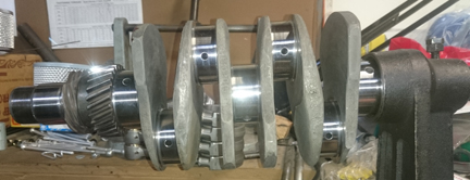
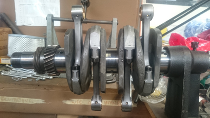
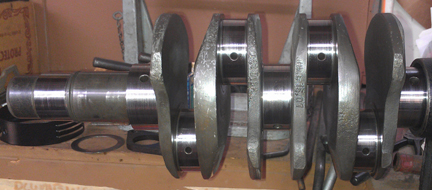
and Connecting RodsAs I always do, the crankshaft was magnifluxed to check for cracks. (I will never put an engine together without checking unless it's literally a brand new crank.) It checked out as OK, but in the process the timing gears were removed and it then became obvious that whoever had ground this crankshaft in the past didn't bother with taking the gears off before doing that work! That's lazy and sloppy, but you can get away with it. The crankshaft was already at "10/10" (0.25mm has been removed from both the main journals and the rod journals) and, thankfully, was still OK to run at those sizes. I also balanced the crankshaft and the journals were polished.
ABOVE RIGHT: This crankshaft after magniflux and polishing, with the gears re-installed. Here you can more easily see that it's a real SC crank and not a later 912 crank. The difference is the webing between rod journals 3 and 1 and between 2 and 4; it's got a longer slope of transition. (...Here's a photo of a 912 crank to compare with!)
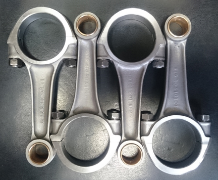
I rebuilt the rods, of course. All these are "late type", the best of the breed.
 For
me, "rebuilding the rods" means to:
For
me, "rebuilding the rods" means to:
This is all standard work so there aren't any photos of them in-process.
ABOVE RIGHT: The rods that went into this engine ready for installation.
BELOW LEFT: The crankshaft for this engine, now ready for installation.
As I don't usually do this, it's worth pointing out that I installed new cam followers. Hey, they were already purchased, and if not put in an SC engine, in what, then?
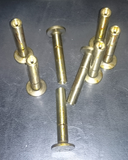
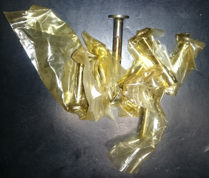
ABOVE, LEFT & RIGHT: The new lifters, emerging from their original packaging. I used hot water and a rag to get the cosmoline off! And, I checked that they were not clogged, just to be sure.
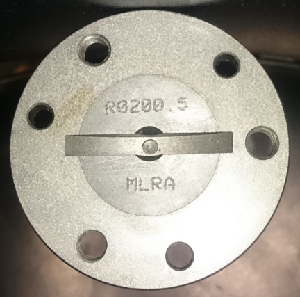
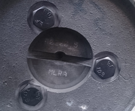
BELOW LEFT AND RIGHT: The camshaft is a brand new wide lobe R0200.5 replacement cam. This was the factory's choice. This one is perfect.
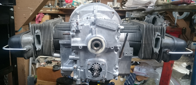
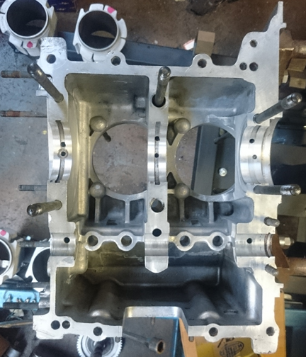
BELOW LEFT & RIGHT: This case cleaned and ready for assembly, the left half already mounted in an engine stand. Unfortunately, the flash was turned off for the left half, while the right is more fully visible, but it does serve to illustrate how much the flash brightens things up! Note that the same effect makes the heads look rather dull grey and not black!
Pop in all four bearing halves (bearings 2 and 3), the dowel pin for the thrust bearing (bearing 1), lay it all in there and fit a timing gear...
 As
usual, I selected a perfectly fitting timing gear from my carefully sorted selection.
As
usual, I selected a perfectly fitting timing gear from my carefully sorted selection.
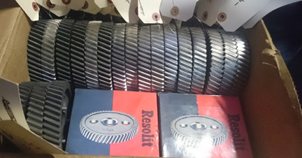
Now, time to put the case halves together! Prep-work done correctly, this goes easily and quickly and the story is best told in images. Note that I used genuine 14mm ATF (across the flats) bolts and nuts, and 12mm ATF nuts on the timing cover, all replated in clear cadmium, though none of these were mounted in the photos in this section!
ABOVE RIGHT: Here we lay the parts in place and then try and find the perfect fit camshaft drive gear. Once one is selected, the gear is mounted using thread locking compound on the bolt threads to ensure it stays together. Then, only the camshaft end plug is required before assembly.
 Not
that it means much, but you can just barely make out in these two images (above
right and below left) a switch out of the engine stand in use. We'd just gotten
several more and were trying them out. The one in the image below left is an
odd and very rare aluminum Belzer head mated with a original VW / Porsche Matra
brand yoke. I made all the carts and at two new stands to which the heads are
bolted. The Belzer is a winner, the other is not!
Not
that it means much, but you can just barely make out in these two images (above
right and below left) a switch out of the engine stand in use. We'd just gotten
several more and were trying them out. The one in the image below left is an
odd and very rare aluminum Belzer head mated with a original VW / Porsche Matra
brand yoke. I made all the carts and at two new stands to which the heads are
bolted. The Belzer is a winner, the other is not!
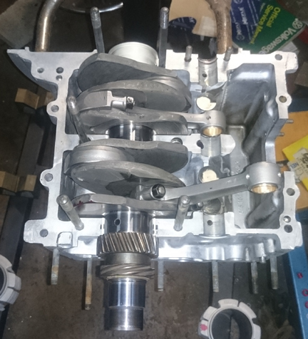
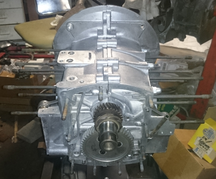
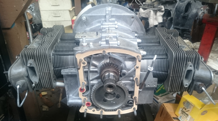
LEFT & ABOVE RIGHT: This engine as a "short block," minus the timing cover, with parimeter bolts not yet installed.
As described earlier, I am preparing this engine for the optional use of the Precision Matters full-flow oil filter system, so I machined the timing cover, but hadn't completed that work at the time the two halves went together, so...
Minus the timing cover, here we have it as a "bottom end" - some would call this a "short block."
I was a little eager about taking photos and hadn't yet gotten the perimter bolts attached! They should be tightened within the first few hours of having the halves attached while the sealing compound is still very wet though it doesn't really cure until it goes through a heat cycle.
 Pistons
and Cylinders
Pistons
and CylindersOriginal SC / 912 cylinders in runnable condition are quite rare today because the process of casting the aluminum fins over the iron liner during the manufacturing process naturally anneals the iron liner, so it's softer than it's all-iron cylinder counterpart, and thus wears faster. And so by now, fifty years later, nearly all of them are worn out! Five to 7 years ago, we finally got a new piston and cylinder manufacturer who is paying attention to our market, and their products are now proven in service. And, lucky for SC enthusiasts, in just in the last year or so, they've added these "Big Bore SC" piston and cylinder sets.
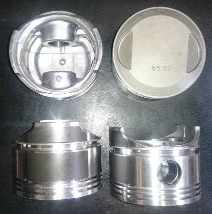
AT RIGHT: This engine's set of Big Bore SC pistons.
MISSING PHOTO: Forgot to take an image or two of the cylinders! But don't worry, you can see them in lots of he images here, starting with the next image below!
We always check the match pistons to cylinders and match piston weights as a set, and provide any remedial action to correct any errors before installation. For example, by shuffling around the piston pins among the pistons, one can usually improve the matching of piston weights. This set started out mis-matched by around 2 grams, but naturally balanced by mixing and matching which pin went where (without removing material) to within 0.5 grams - the official specification is ten grams (10g). Because one was much ligher than the others, I opted not to remove a lot from all three others - 0.5g is still very very good and is around the weight of three drops of oil!
 For
many shops, from this point, installation goes very quickly, but we think this
is where one needs to take one's time! The key reason one needs to take time
here is that there are production tolerances on every part in an engine, and
while a set of parts may look identical, there's often subtle variation between
members of a set, and there are sometimes significant errors in production
that weren't caught by the manufacturer's quality control processes. These errors
can "stack up" and cause problems if not discovered and corrected.
For
many shops, from this point, installation goes very quickly, but we think this
is where one needs to take one's time! The key reason one needs to take time
here is that there are production tolerances on every part in an engine, and
while a set of parts may look identical, there's often subtle variation between
members of a set, and there are sometimes significant errors in production
that weren't caught by the manufacturer's quality control processes. These errors
can "stack up" and cause problems if not discovered and corrected.
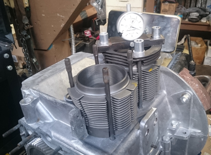
AT RIGHT: This engine's cylinder 3 is being checked for the CAC value.
Here's our process: Two of these steps require special tools most shops don't have.
 We
like to carefully measure everything and then mix-and-match the parts for superior
fit. We have also discovered significant manufacturing errors with this process
which would likely have gone unnoticed without these measures. It is remarkably
easy, for example, to overlook the circumstance of the crankshaft bore not in
the true center of the crankcase, angled on the horizontal left or right of
center, or not on the same horizontal plane at all. Yet examples of errors like
these are not as uncommon as we would like.
We
like to carefully measure everything and then mix-and-match the parts for superior
fit. We have also discovered significant manufacturing errors with this process
which would likely have gone unnoticed without these measures. It is remarkably
easy, for example, to overlook the circumstance of the crankshaft bore not in
the true center of the crankcase, angled on the horizontal left or right of
center, or not on the same horizontal plane at all. Yet examples of errors like
these are not as uncommon as we would like.
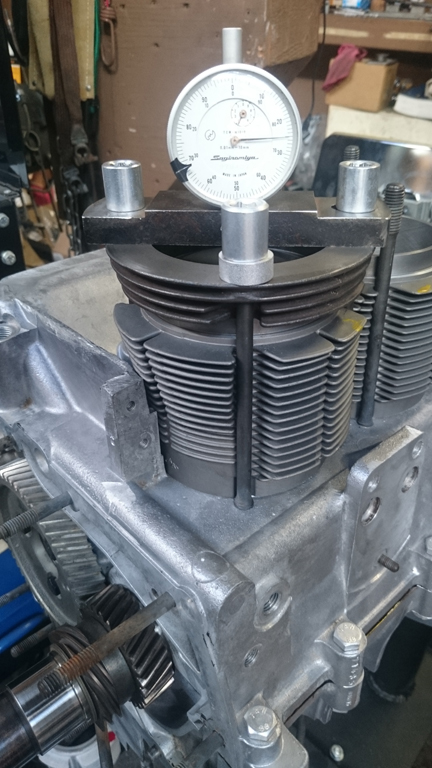
AT RIGHT: This engine's cylinder 4 undergoing a CAC check. Note the difference in the dial reading from #3 above. The small divisions on the dial are 0.01mm - less than a half a thousandth of an inch - and the major divisions are 0.1mm, or about 0.004. These differences may appear minor but reveal a great deal and provide a wonderful opportunity for improvement; in this instance there was around a 0.1mm difference in piston pin heights and by swapping 3 and 4, the effective combustion chamber volumes were brought much closer to perfection.
Missing is an image - I usually take! - of them being fitted for height comparison check - this is done to ensure that there are no difference between the cylinder heights that the head itself "sees." The book value for tolerated error is 0.1mm (four thousandths of an inch). (Here's an image of doing the cylinder height check for another engine in our workshop.)
The next thing we do is something nobody else does (that we know of) in the engine building process, and that is to measure the height the piston crown comes above the plane of the top of the cylinder. I call this the CAC, or "Crown Above Cylinder." This value is important because, firstly, it can reveal deeper problems, and because it helps us get the compression ratio equal in all four cylinders.
Here are some of the deeper problems that can be discovered through a CAC check:
In order to do this for these engines, you have to have special tools. Here, you can see them in action on this engine in the two images above.
As noted in one of the imge captions, even if you can't read the needle in these images, you can tell that there's a difference between cylinders 3 and 4 above. The distance between the smallest tick marks is one hundredth of a mm, or 0.0004", and you can discern to perhaps a tenth of that! So, this is a very accurate measure, performed while the cylinder is under torque, so any shims are squished flat, etc.
The accuracy is so good, that if you take the time to swap parts around, you can accurately determine discrepancies in the manufacture of the various parts! But, we ARE splitting hairs here! However, a benefit to both engine builder and customer is that the ability to move parts around for better fit means that perfection is more easily achieved, and the more equal the HP production of each cylinder, the smoother the engine will run, and the more HP the engine will produce overall.
Because this process includes the entire assembly, torqued as in service, and measures the height each piston protrudes out of its cylinder, all errors in connecting rod lengths, cylinder heights, crankcase spigots depths (cylinder bore deck), piston connecting pin heights, and shim thickness' are accounted for in the measurement results. There is no superior method.
In this instance, both the cylinder spigot heights (the case bores below the cylinders) and, subsequently, the cylinder heights, were close enough to have no measurable difference to their mates. (This is unusual!) Due to mismatch in CAC values right to left, the left cylinders (3 & 4) were shortened, heights checked again, and 0.2mm shims installed on the right (1 & 2) to bring the whole set, in combination with the cylinder head volume sizes, to a 9.4 : 1 compression ratio.
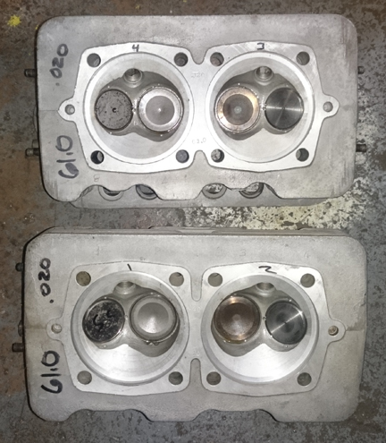 Overall
these heads are a very nice original pair, with no cracked combustion chambers
or fins or stripped threads. And, SC heads are remarkably rare - the black coating
(not anodizing, but often confused for it) is unique to them and the S90, and
it can be (and sometimes is) cleaned away because it isn't very durable! In
theory, when new the black shading increases the emmisivity of the head by about
9%. Unfortunately, these heads have been cleaned rather much such that they've
lost a good bit of their blackness, though they retain more than tends to show
up in these images because the flash used tends to wash-out the darker coloration.
Overall
these heads are a very nice original pair, with no cracked combustion chambers
or fins or stripped threads. And, SC heads are remarkably rare - the black coating
(not anodizing, but often confused for it) is unique to them and the S90, and
it can be (and sometimes is) cleaned away because it isn't very durable! In
theory, when new the black shading increases the emmisivity of the head by about
9%. Unfortunately, these heads have been cleaned rather much such that they've
lost a good bit of their blackness, though they retain more than tends to show
up in these images because the flash used tends to wash-out the darker coloration.
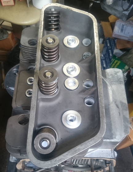
AT RIGHT: These heads' combustion chambers, ready for installation. As noted elsewhere, the flash makes the heads' black coating nearly disappear. This is caused not only by the flash but also by fading of the original coating due to the effects of cleaning - the black coating is not very durable.
As stated above, we found no cracks, however, we did find bunged up guides. But, no matter, as usual, we replaced all 8 valve guides with modern materials that take our unleaded fuels better than the old guides did.
We also found the heads needed to be flycut. They were already cut some without the outer surface having been refaced - a real no-no, but they got away with it because they didn't cut too much. We did the job right and after flycutting the sealing surface we also faced the outer surface and did a conical cut in the head to return them to their original chamber sizes of 61ml.
MISSING IMAGES: Ordinarily we take photos of the tops, bottoms and rocker chambers in addition to the combustion chambers seen above. This was a simple oversight. Oops! But happily, you can see all those areas in other images shown on this web page, just not exclusively in photos of cylinder heads! We regret the oversight...
Fitted to these heads are great valves. They're originals, not aftermarket replacement which are all you can get new today. Further, and vitally, all the exhaust valves ARE the sodium filled type, which haven't been available new for some years now, and two of the intakes and two exhausts are new! Of course, the used valves valves have been checked for length (stretching makes them unworthy), polished, and refaced, so they're effectively perfect. The new valves were selectively installed in those combustion chambers where being a tiny bit smaller would help improve the match of all four cylinder's compression ratio - every little bit helps!
New springs, of course, carefully selected.
We match up slightly stiffer springs with the heavier valves (intakes are about 2% heavier than exhausts), so they're very close sets, matched up, so all the valves tend to float at the same time. ...Of course, each valve and retainer are position-specific through the shimming process...
After the valves are fitted, the combustion chambers are measured with a burrette. Remarkably, all four combustion chambers measure 61.0 ml.
 At
this point the engine is ready for its cylinder heads, and this work went very
quickly - as it should! - as all the prep work was already done.
At
this point the engine is ready for its cylinder heads, and this work went very
quickly - as it should! - as all the prep work was already done.
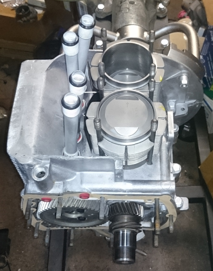
AT RIGHT: This engine, ready for the left head to be mounted.
Prepare the head "bolts" and washers, prepare the pushrod tubes, prepare the lower cylinder air deflection plates and their wire retainers, and get the torque wrenches set, and bolt on those heads!
My pattern is to mount one head, torque it to 7 ft lbs (as per the early manual), then mount the other head the same way, and then alternate between the heads with an ever-increasing torque up to the final torque value, then repeat the final value until the fasteners no longer turn when torque is applied. It's a gentle approach and tends to avoid cylinder head leaks.
BELOW LEFT & RIGHT: Both heads, installed. Here, the flash didn't wash-out the color of the heads as much and you can better see the blackness Porsche installed on SC (and Super 90) heads. The black rejects heat better, reportedly there's a 9% difference, though that does presume the metal is clean! It's not entirely clear what the process of blackening was because it's not very durable. In any event, also notice here the mounting hardware was replated as well.
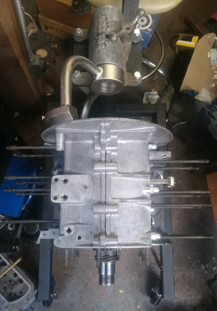
The timing cover was in the mill getting that notch cut for the full-flow oil system, so I continued on without the cover attached. Now, with the cover ready, it got installed. Here's the engine just before that happened.
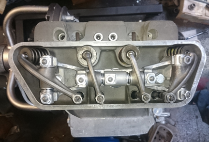
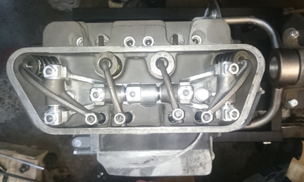
OK, mount the valve gear, adjust the valves and pop on the valve covers.
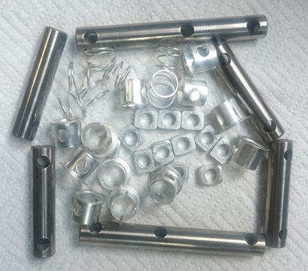
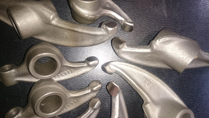
LEFT & ABOVE RIGHT: The rocker shafts have been polished, the spring and mountnig hardware plated, and the rockers themselves have been "hard faced" and then resurfaced. "Hard-facing" is a process to renew the hardness and thickness of metal that forms the surface that contacts the valve stem. A hard material is welded onto the iron rocker face and then it is resurfaced using special tooling to get the arc correct.
We can't forget the flywheel! It was properly taken care of too... I don't always include a pressure plate with a long-block, but in this case...
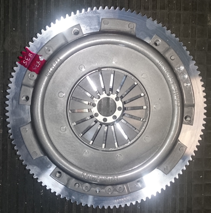
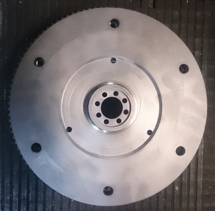
ABOVE LEFT & RIGHT: The flywheel for this engine is an original 200mm unit with 6 volt ring gear. It has been blasted clean and then machined - "resurfaced" - where needed. Mated to it is a correct original pressure plate, doweled in position and rotationally balanced.
 Then
fit the oil drain plug, and sump screen and plate. Of some small note is that
all the sump studs are original and in fine condition. I used new cap-nuts to
protect the studs into the future. Then, fit the two oil control pistons, their
springs and retaining caps.
Then
fit the oil drain plug, and sump screen and plate. Of some small note is that
all the sump studs are original and in fine condition. I used new cap-nuts to
protect the studs into the future. Then, fit the two oil control pistons, their
springs and retaining caps.
And now here it is as the longblock, ready for pickup or delivery!
NOTE: If this engine is sold as a long-block... One should NOT install the distributor drive gear without also installing a distributor because if anyone rotates the engine backwards, it will push the drive gear up where it can damage the bronze drive gear! Therefore, the distributor drive is NOT mounted until the last reasonable moment!
Because some people are keeping logs of VIN and engine numbers and then purport to tell people what someone else has, out of respect and concern for a buyer's privacy, exact VIN and engine number data are not published here.