Copyright © 2007 - 2025, Coachworks For contact data Click Here.
Copyright © 2007 - 2025
Copyright © 2007 - 2025,
Coachworks For contact data
Click Here.
![]()
![]()
 This
engine has had an extensive rebuild following an explosive event - it threw
a rod!
This
engine has had an extensive rebuild following an explosive event - it threw
a rod!
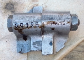
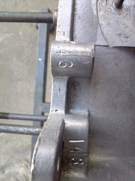
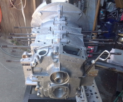
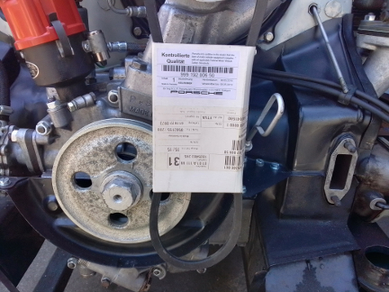
AT RIGHT: A lovely souvenere nobody wants. This is a perimeter bolt boss on the top, the second forward of the timing cover, and it contains the "case casting number" 69426 on the left half, and the engine type number 616/16 on the right half. All assembly-line cases have these numbers, but we're rebuilding this engine with a replacement pair of halves where these numbers were never stamped and are not present - a proper repair.
 This
engine came to us with a hole in the case, needing a new pair of main case halves...
Here's its story from when it came to us.
This
engine came to us with a hole in the case, needing a new pair of main case halves...
Here's its story from when it came to us.
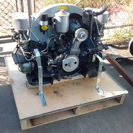
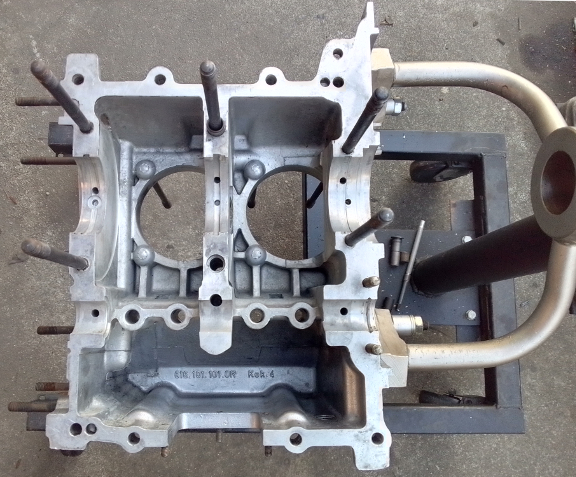
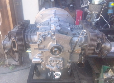
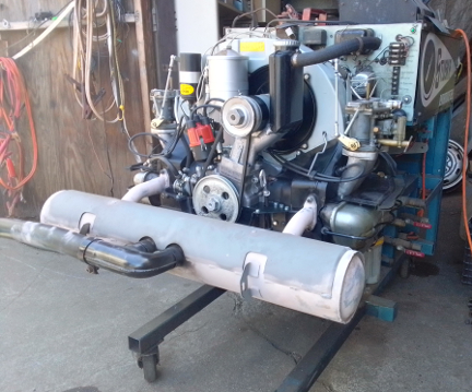
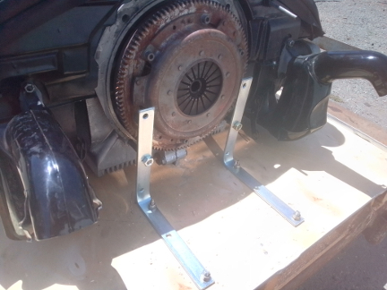
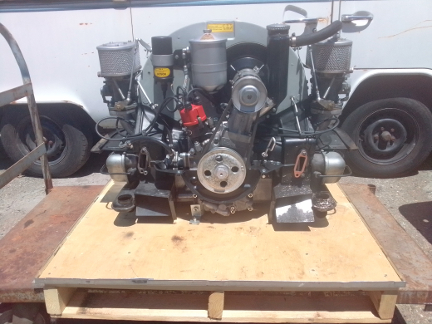
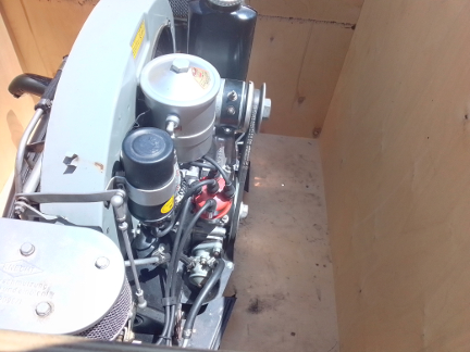
AT RIGHT: This engine as we received it, having just removed the upper portion of the crate. ... That's not how we advise bolting one down as there are easier ways, but it worked fine...
We got a call from a Porsche dealership who was looking for a case to build their customers exploded engine into. They found us, appropriately, but we aren't a parts house and, as a general rule, we don't sell parts not in conjunction with some kind of service work - that's generally why we got the parts in the first place, be ready to handle just about any kind of repair work.
They were in luck as we usually have some cases available, and in this instance had a matched pair of appropriate case halves that were not used on an assembly line but rather were sold as a replacement case. ... We have a few, at the moment.
We were told the engine had been run without oil and that's why it had thrown a rod, but the evidence said something else, as we'll see below.
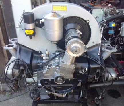
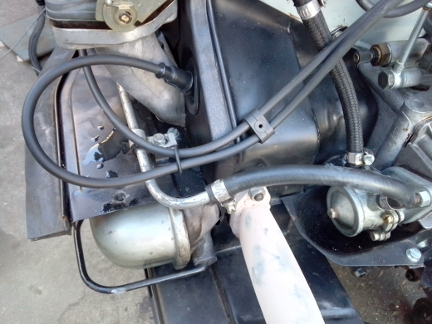
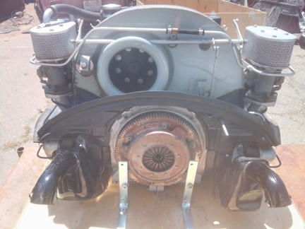
 Overall,
it looks pretty good, and is more complete and correct than many in this day
and age. Notable are solid-shaft Solexes, and the nearly-never-seen-today cloth
braided breather hose!
Overall,
it looks pretty good, and is more complete and correct than many in this day
and age. Notable are solid-shaft Solexes, and the nearly-never-seen-today cloth
braided breather hose!
AT RIGHT: Here, the attachment to the case, using the engine to transaxle mounting studs, is the way we do it on this side - simple, and works great! Meanwhile, the engine was in reasonably good form and also fairly clean.
...One could nit-pick it, but then, this isn't a concourse event and it's best to just admire it for what it is; a -ahem- survivor!
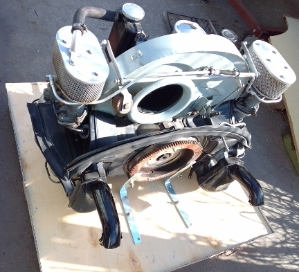
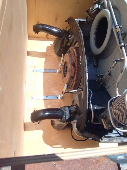
This poor thing got trashed from the inside. You've seen the outside, now, here's what we found as we dug deeper in.
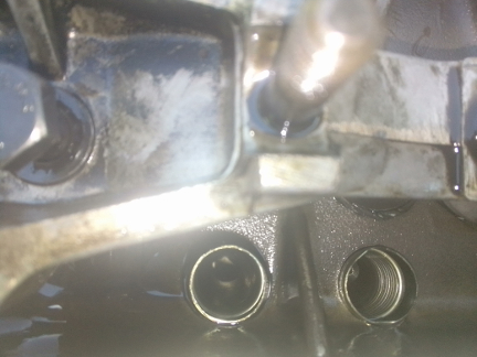
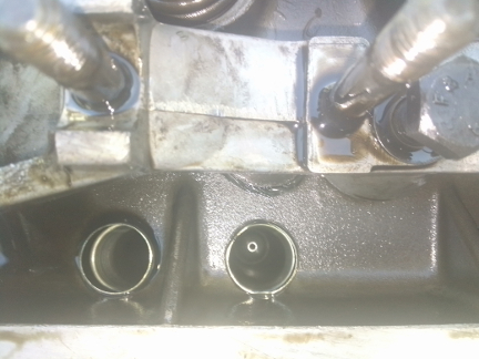
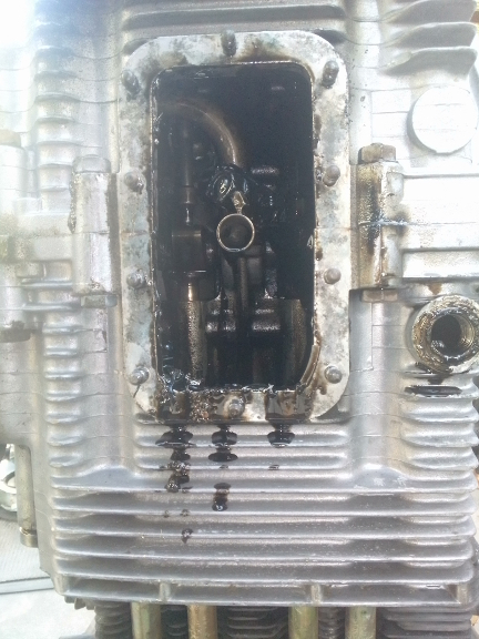
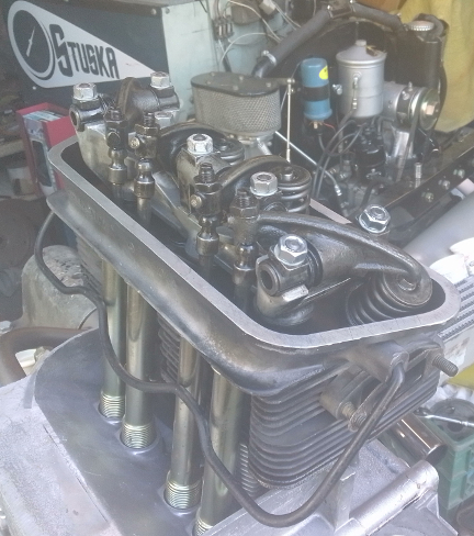
BELOW: Everything looked normal until we got here, the cylinder head for cylinders 1 and 2; cylinder 2's pushrods are AWOL!
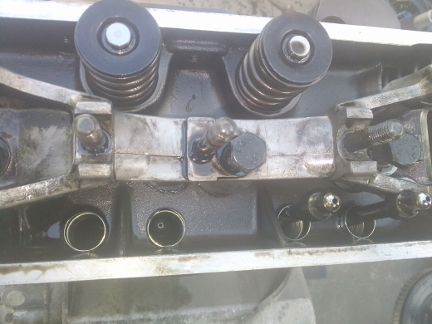
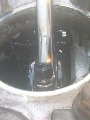
BELOW: Here we peer into each pushrod tube for cylinder 2, exhaust on the left, intake on the right. ... The exhaust pushrod is completely missing! The intake is visible, hiding deep inside!
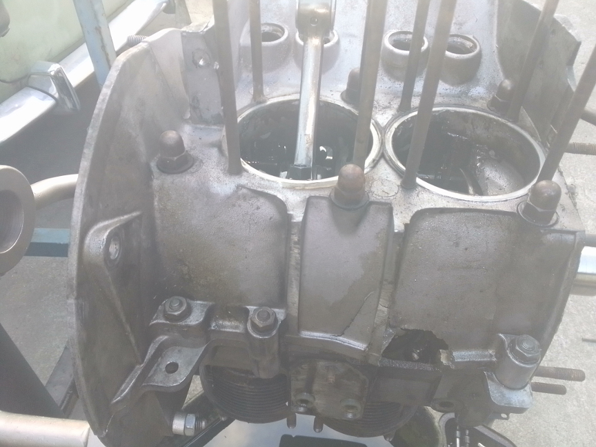
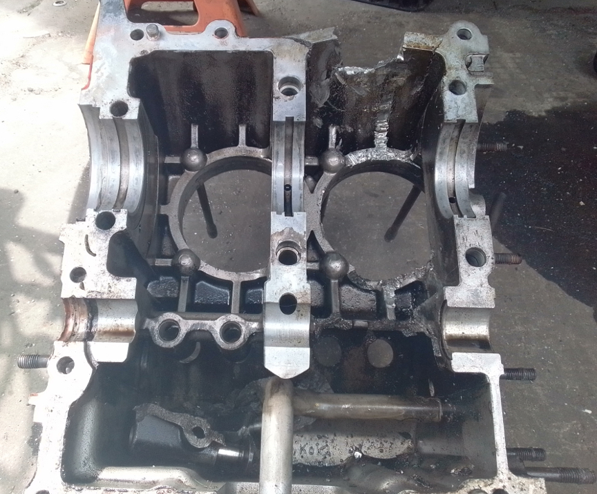
BELOW: Then, there's the big hole in the top of the case. Now that everything is out of the way, we can get a better look. Note also the letter L stamped into the rod! This is a BIG no-no! This one is stamped on the highest stressed part of the rod, but all three surviving rods have this same stamp in about the same spot. A stamp like this very well could be the cause of failure of the rod for cylinder 2.
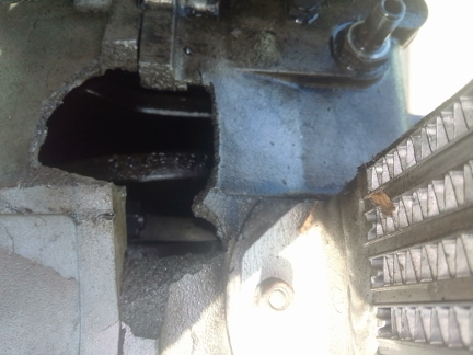
BELOW, LEFT & RIGHT: On left, the hole in the top of the case, actually taken before the image above. Yes, that's the crankshaft visible through the case hole. On the right, this "L" stamp is on the rod for cylinder 1, also seen above. And, as noted above, a stamp like this could have been the reason for the disaster.
BELOW, LEFT & RIGHT: With the sump plate and (trashed) screen out of the way, we can get a better look.
One thing that is kind of remarkable is how black the oil is. Yes, a failing engine like this will spill combustion byproducts into the case and can blacken the oil, but no, this is long-term neglect! Don't let this happen to your oil - it's cheap! When the oil on the dip stick looks dirty, change the oil! And, if the oil seems to get dirty quickly, most likely the piston rings are failing and letting "blow-by" into the case.
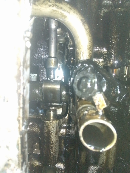
We also see here, better in the close-up at right, how the lifters are simply missing for cylinder 2 and yes, the pushrod is riding directly on the camshaft right now! But then, it's aided by gravety.
The weird nut-like thing above the oil pickup tube is the rod cap for cylinder 2's rod!
BELOW: Once the case was apart, we can finally survey all the damage to the case's guts.
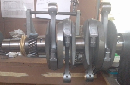
About all that's left to see of the damage was the crankshaft, and the rod itself. First, the crank.
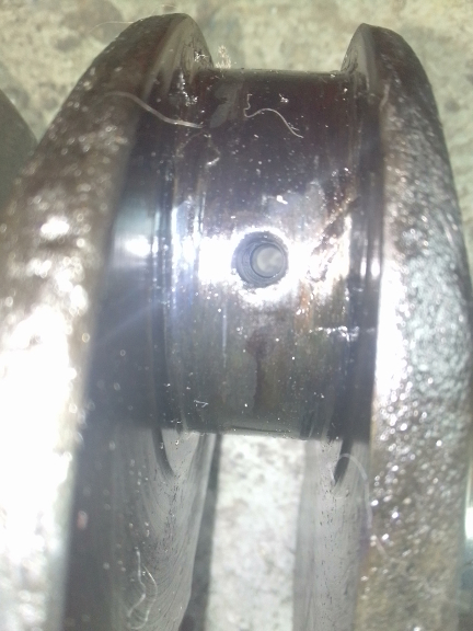
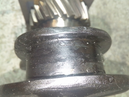
BELOW: Unfortunately, the damage to the crank is hard to capture in photographs, however, here we've tried our best. The blackness is actually metal! The rod bearing apparently melted into the rod journal, blending the two. Unfortunately, the crank was bent more than a little and is likely cracked, so rather than investing a substantial chunk of the cost of a new one only to possibly discover it's junk, we just replaced it. That gear (seen the right image), however, we reused on the new crank, of course!
Now, we need to get images of the rod posted, and we'll be done!
We'll get to it soon as we can!
 The
case halves chosen are an un-numbered pair from a replacement case. They're
un-numbered in that there's no "case casting number", no "type
number" and no "serial number", though there is, as always, a
"match number." You can read up on
case numbering and replacement cases here, but in short, replacement cases
weren't assembly line items but were secured from dealerships later to repair
a significant problem when shipping the whole engine back to Stuttgart was impractical.
The
case halves chosen are an un-numbered pair from a replacement case. They're
un-numbered in that there's no "case casting number", no "type
number" and no "serial number", though there is, as always, a
"match number." You can read up on
case numbering and replacement cases here, but in short, replacement cases
weren't assembly line items but were secured from dealerships later to repair
a significant problem when shipping the whole engine back to Stuttgart was impractical.
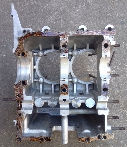
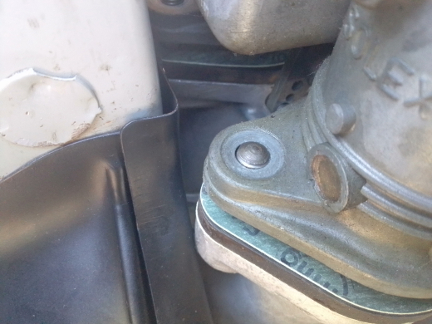
AT RIGHT: This is half of a "replacement case" from 1970. It's "un-numbered", having never been used on Porsche's assembly line but rather was an available spare part - it's a perfect choice for repairing this otherwise "matching numbers" engine that is original to its vehicle it was in when damaged.
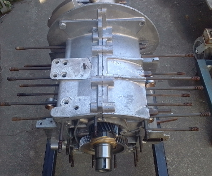
The new main bearings were checked for fit into the case and upon confirming they have proper "crush" (that is, the right amount of "interference fit" as the bearing is a tiny bit bigger than the bore in the case where it belongs), the case was then cleaned thoroughly. It was inspected and some of the studs were found wanting. ... Several studs were replaced, and it was then ready for assembly as seen here.
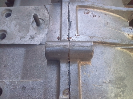
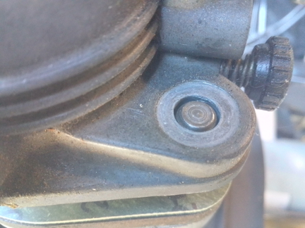
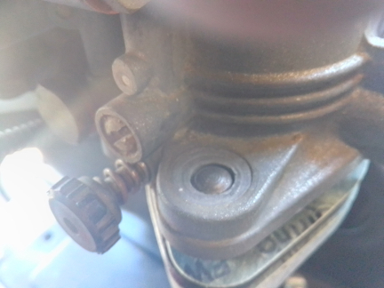
BELOW, LEFT & RIGHT: At left we show the boss cast into the case which usually receivces the case casting number on the left half and engine type number on the right, but here it's clearly blank - never stamped. And, interestingly, this case, cast as it was after the assembly-line automobiles had become a thing of the past, was cast during the 911 era and the person who stamped the match-numbers into the case was apparently unfamiliar with where to stamp new 356 and 912 cases! BOTH halves of the case had their match numbers struck on the wrong boss, then corrected by re-striking on the correct one!
Later in production, more near the end of the 912 era, timing covers and case halves were machined a bit more accurately with timing covers bored separately from the halves, but at this point in production, the three constitute a triplet, with the crankshaft's main bore done for all three in one operation. As this crankcase triplet is made up of a matched pair of halves with a non-matched timing cover, it wasn't expected that they'd line up, and, as anticiapted, the bearing bores were not concentric.
There are many ways to resolve this, including boring all three together as was originally done. But with that technique, the timing cover itself need to be overbored and as the timing cover is not normally overbored, there are no sets of bearings which provide for this, so a new bearing will have to be made, or one for a different application modified. In this instance, the non-concentricity error was very small - < 0.4mm out, or, in inches, about 0.012" off. That's enough to be a problem if not corrected, but not a serious problem to correct. Since the nose bearing (#4) is solid aluminum and carries no significant load, burdened only with keeping the nose of the crank from whipping around, helping keep vibration from upsetting cam and ignition timing, our favorite method to solve this problem is to simply make a new nose bearing and bore it off center, rather than overboring the timing cover. ...Unfortunately, we were "on a roll" and didn't think to take any photos of our work, but the results are a perfect fit, as proven by the running in on the dynamometer for around two hours of run time!
As it's more efficient to do rods as batches, we try to do so, and in this instance, we chose a set from this batch:
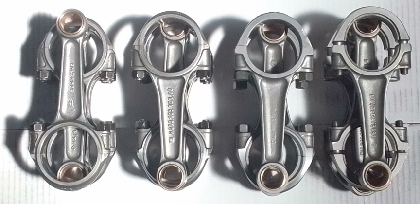
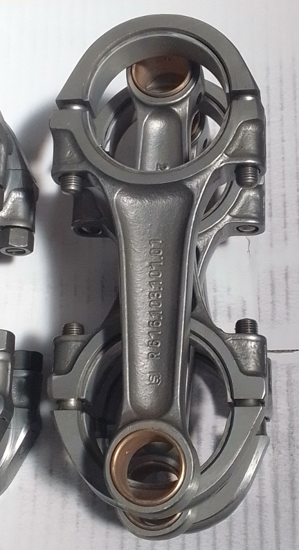
AT RIGHT: We chose this set from among the above sets. These are the last type, the best plain-bearing rods Porsche ever used. Of course, they're already "rebuilt" to our exacting standards.
For us, "rebuilding the rods" means to:
This is all standard work so there aren't any photos of them in-process.
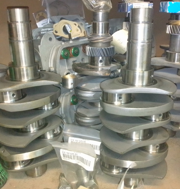
As the crankshaft was destroyed by the rod-throwing incident, we selected a new one. We happen to stock these new reproductions - these are the same ones Stoddard and all the other main retailer's sell. They're forged, made from a tough alloy of steel and feature a threaded drilling plug for easy cleaning in the future - something the originals lack.
AT RIGHT: We chose one of these two new 912 / SC reproductions seen here. We also selected the camshaft encased in the green sleeve seen at the lower left corner - it was inadvertently cropped out of this picture! Oops! Oh well. ...These are fine cranks...
As usual, we mounted the crankshaft up on the ole crankshaft stand and mounted up the rods.
BELOW: The chosen crank from above, with the chosen rods, also from above, now mounted and ready for installation in the case.
Next, one sets the half-bearings, any dowel pins, etc, in the case, then the crankshaft, and check the fit of the camshaft gear. A camshaft gear is then selected and it's then more permanently afixed, generally via thread sealant or lock tabs or whatever your favorite is - we prefer mid-grade thread sealant.
Once a camshaft gear is selected, one then oils up and inserts the lifters, and "paints" the perimeter with one's favorite sealant - we use Permatex Aviation Grade, the same as both Porsche and VW did for their assembly-line engines. We only put it where it's needed - and as thin as we can and still get good coverage.
The camshaft is worthy of some note. It's a "wide-lobe 912," known as the Ro200, and is the "replacement" camshaft Porsche chose to supersede the earlier design in its SC and 912 engines. This cam has a tiny bit more lift and substantially longer open duration, and is known for having substantial low-end torque and a flat curve, all the way up to the same peak HP and torque RPM numbers as the earlier version of this cam.
This particular cam is a new one as the old one was also an Ro200 but had some scoring on it that, while "regrindable" in theory, doing so would, according to our camshaft grinder, reduced the "heel" of the cam too much due to the increased speeds required to open the valves fast enough. Oh well, it's just part of the damage caused by "throwing a rod."
Also worth pointing out here that we refaced the cam followers, of course!
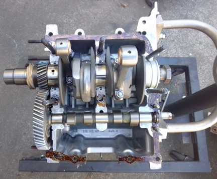
Now, time to put the case halves together! Prep-work done correctly, this goes easily and quickly and the story is best told in images:
 The
heads are genuine SC heads, and they were already in pretty good shape. The
guides had been recently replaced and had very little wear, except that someone
had installed valve stem seals - which ARE included in the modern gasket kits
- on the intake valve guides when they should not have been. These are for worn-out
guides to help delay the need for replacement! They are NOT intended for new
guides. ...And so, the guides had a bit more wear than they should have had
because they weren't getting their usual oiling, however, this hadn't been going
on for very long and we deemed it not worth the stress on the heads to R&R
the guides.
The
heads are genuine SC heads, and they were already in pretty good shape. The
guides had been recently replaced and had very little wear, except that someone
had installed valve stem seals - which ARE included in the modern gasket kits
- on the intake valve guides when they should not have been. These are for worn-out
guides to help delay the need for replacement! They are NOT intended for new
guides. ...And so, the guides had a bit more wear than they should have had
because they weren't getting their usual oiling, however, this hadn't been going
on for very long and we deemed it not worth the stress on the heads to R&R
the guides.
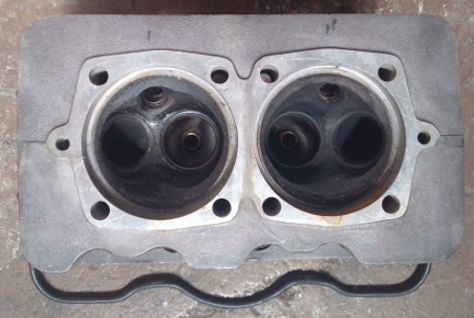
AT RIGHT: This head had been on the right side, for cylinders 1 and 2. Note the dark colors of the valve seats; they're coated with carbon, indicating that combustion occurred while the valves were open. (See text for more on that.) We re-ground the seats for a good sealing surface.
However, as can be seen here, there's carbon over all of the valve seats indicating all the valves have been open when combustion occurred. This can only happen when the valve adjustment is too tight. And, as valve clearance increases when the engine warms, we can conclude rather definitively this engine's maintenance had been ignored.
 Thankfully,
the heads did not need to be decked as it had been done recently (mileage wise).
Thankfully,
the heads did not need to be decked as it had been done recently (mileage wise).
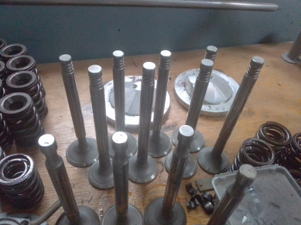
AT RIGHT: We always reface all valves that have been in service before reinstallation. ...Note that the four valves in the foreground are NOT for this engine - those are single-keeper groove type, used through the end of the B series in July, 1963.
Before sending them out to be refaced, we measured the exhaust valve for cylinder two, the cylinder that had the rod fail, and found the valve bent. So, we asked our valve grinder to please check them all, and he provided us with replacements for the bent ones. We measured the tension of the valve springs and found them suitable for 6000 RPM but not beyond! (95 lbs at the seat - we like to see 100+ for engines that will rev beyond 6k RPM, but higher spring pressures also equal more wear and a little bit of lost BHP).
Upon reinstallation we found that more valve shimming was required on at least five valves, as much as a whole mm on at least four of them) (we say "at least" because we weren't recording it at the time, just noting this afterward) and this puzzled us - it indicates that perhaps the valves were shimmed a bit shy, and therefore the springing was a bit weaker, than it should have been during the previous rebuild, which can help explain the bent exhaust valves.
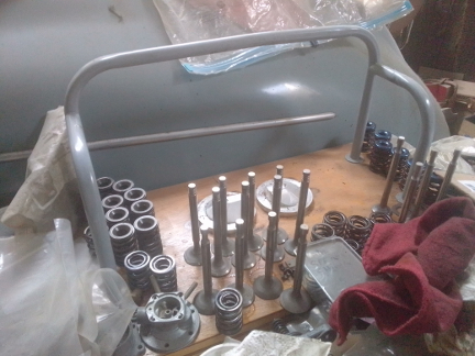
BELOW: This image shows the valves and our work area where we disassemble and reassemble heads. The grey tubing and wooden based tool is a special fixture that makes these operations easy, and you can see this tool in the various workshop manuals.
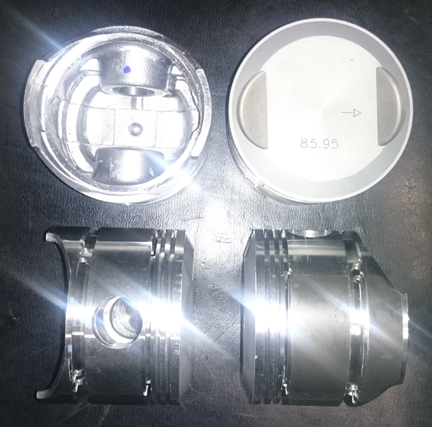 The
former piston and cylinder set fitted to the engine were garden variety "NPR
copies," as we have seen since the 1990s. These are 86mm bore, making 1719cc,
in an iron cylinder with a cast four ring piston. As noted above, they were
irreparably damaged when the rod got thrown.
The
former piston and cylinder set fitted to the engine were garden variety "NPR
copies," as we have seen since the 1990s. These are 86mm bore, making 1719cc,
in an iron cylinder with a cast four ring piston. As noted above, they were
irreparably damaged when the rod got thrown.
AT RIGHT: These are a "stock photo" we have taken of this type of piston set. You can see images of the actual in some of the photos below.
We replaced these with modern "Biral" big-bore cylinders with matching cast pistons. These are also 86mm in bore with four rings, but unlike the previous set, they have an iron cylinder with aluminum fins cast over the cylinder, thus improving cylinder cooling at the cost of some longevity due to the annealing of the iron caused by the casting of the fins. ... This is exactly the same design as the original SC pistons and cylinders, but with a bigger bore (86 vs 82.5).
New parts are not exempt from careful checking!
We always check the match pistons to cylinders and match piston weights as a set, and provide any remedial action to correct any errors before installation. For example, by shuffling around the piston pins among the pistons, one can usually improve the matching of piston weights. This set naturally balanced (without removing material) to within 0.7 grams - the official specification is ten grams (10g) - and then we removed a little more material from the heavy ones so they're all within 0.1g now.
For many shops, from this point, installation goes very quickly, but we think this is where one needs to take one's time! The key reason one needs to take time here is that there are production tolerances on every part in an engine, and while a set of parts may look identical, there's often subtle variation between members of a set, and there are sometimes significant errors in production that weren't caught by the manufacturer's quality control processes. These errors can "stack up" and cause problems if not discovered and corrected.
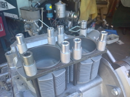
AT RIGHT: Here, the cylinders installed-heights are checked on a per-side basis. In this instance, a difference of 0.005" was found between tallest and shortest, however, they paired up nicely with only about 0.001" difference between either of the two pair.
Here's our process: Two of these steps require special tools most shops don't have.
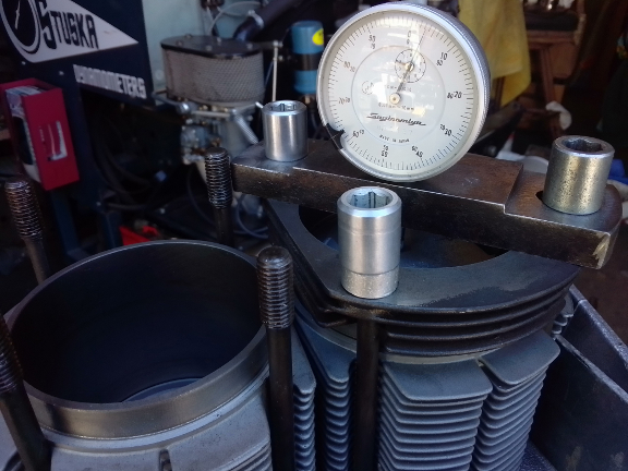
AT RIGHT: Here, the height the crown of the piston extends above the top of cylinder 3 is measured. We call this the CAC check. This measurement is made and recorded for all cylinders and the values are used as indicated in the accompanying text.
Note the biral cylinder design - aluminum fins over iron cylinders!
We like to carefully measure everything and then mix-and-match the parts for superior fit. We have also discovered significant manufacturing errors with this process which would likely have gone unnoticed without these measures. It is remarkably easy, for example, to overlook the circumstance of the crankshaft bore not in the true center of the crankcase, angled on the horizontal left or right of center, or not on the same horizontal plane at all. Yet examples of errors like these are not as uncommon as we would like.
Here (two images above) you can see them being fitted for height comparison check - this is done to ensure that there are no difference between the cylinder heights that the head itself "sees." The book value for tolerated error is 0.1mm (four thousandths of an inch), but in this case, we instantly noticed a discrepancy of over 0.1mm (measured at 0.005"). This is very unusual for this cylinder type, but thankfully, there were two long ones and two short ones, giving a difference of about 0.001" on either side, and 0.004" from side to side, and also it just happened that the difference in the heads was taken advantage of here to get all four cylinders at our target compression ratio. (How'd we do that? Keep reading!)
The next thing we do is something nobody else does (that we know of) in the engine building process, and that is to measure the height the piston crown comes above the plane of the top of the cylinder. I call this the CAC, or "Crown Above Cylinder." This value is important because, firstly, it can reveal deeper problems, and because it helps us get the compression ratio equal in all four cylinders.
Here are some of the deeper problems that can be discovered through a CAC check:
In order to do this for these engines, you have to have special tools. Here, you can see them in action on this engine in the two images above.
The accuracy is so good, you can accurately determine discrepancies in the manufacture of the various parts! But, we ARE splitting hairs here! However, a benefit to both engine builder and customer is that the ability to move parts around for better fit means that perfection is more easily achieved, and the more equal the HP production of each cylinder, the smoother the engine will run, and the more HP the engine will produce overall.
Because this process includes the entire assembly, torqued as in service, and measures the height each piston protrudes out of its cylinder, all errors in connecting rod lengths, cylinder heights, crankcase spigots depths (cylinder bore deck), piston connecting pin heights, and shim thickness' are accounted for in the measurement results. There is no superior method.
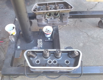
At this point the engine is ready for its cylinder heads, and this work went very quickly - as it should! - as all the prep work was already done.
Prepare the head "bolts" and washers, prepare the pushrod tubes, prepare the lower cylinder air deflection plates and their wire retainers, and get the torque wrenches set, and bolt on those heads!
Our technique is to mount one head, torque it to 7 ft lbs (as per the manual), then mount the other head the same way, and then alternate between the heads with an ever-increasing torque up to the final torque value, then repeat the final value until the fasteners no longer turn when torque is applied.
BELOW, LEFT & RIGHT: We're always snapping images and most of the ones we took of this process were washed out via too much light! However, these were OK. At left, the heads, waiting to be installed, set upon the lower portion of the engine stand. At right, the heads now mounted on the assembly as it was after the cylinders had been mounted. Perhaps notable is that the blackening of the heads can be seen to be robust within the rocker-box area of the heads but a bit faded out on the rest of the head. This fading is usually due to the rough actions of simply cleaning the heads performed by previous mechanics. However, in our case, we try very hard NOT to contribute to this kind of fading, primarly by avoiding unnecessary cleaning, and when necessary to clean, doing so in a very gentle way.
Now, the rocker gear is up next...
Now we have a proper long-block; clean the valve covers, install them, and begin the rest of the installation!
BELOW, LEFT & RIGHT: Here, we have our just completed long-block already turning the corner to become a complete, running engine. First up was the oil cooler, which we previously flushed through a three step process to ensure there are no "foreign objects", such as metal bits, left over from the thrown-rod incident. We had done this already before we got to the timing cover, but this flushing process was proven necessary when we found the oil pressure control piston's bore in the timing cover clogged with metalic debris from the rod beign thrown; the oil system WAS substantially contaminated with debris from the event.
 This
phase usually goes quickly, and here we were only delayed by a few things. ...Most
all the items in this section are the oddball things we had to spend extra time
on!
This
phase usually goes quickly, and here we were only delayed by a few things. ...Most
all the items in this section are the oddball things we had to spend extra time
on!
First, we found that the small steel angle bracket that retains #2's cylinder shroud had a bad thread. Someone had cross-threaded a screw in it, but this was easily fixed with a tap, once we realized this was the problem.
Secondly, we apparently misplaced the left-hand engine bay closing panel. A thorough look yielded nothing. Know it's here somewhere and that it's not vital for runnin-in the engine, we proceeded anyway, and as soon as we stopped looking for it, it turned up! But, we did waste a lof of our own time on it!
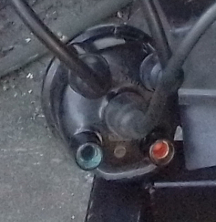
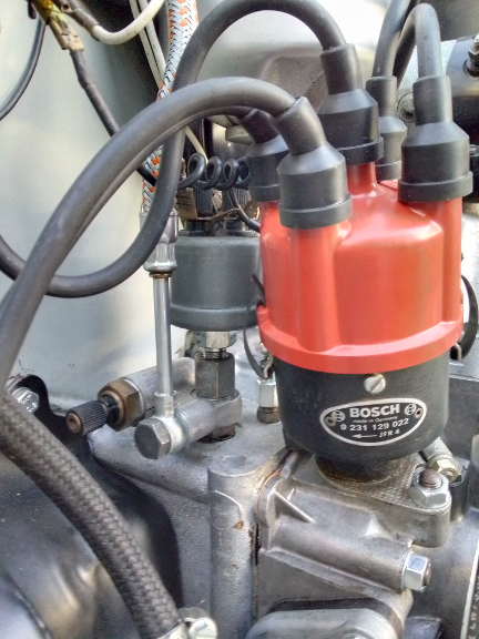
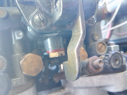
AT RIGHT: Notice anything odd, though? Yes, the alert will notice the corrosion in the distributor cap's hole for cylinder 1's ignition lead! And, yes, cylinder 1's ignition lead is likewise corroded! So, new cap and wires are in order...
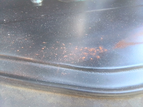
BELOW: Close-up of the distributor cap... This corrosion was on-going for some time! How it got that way only the engine's primary care-taker could know!
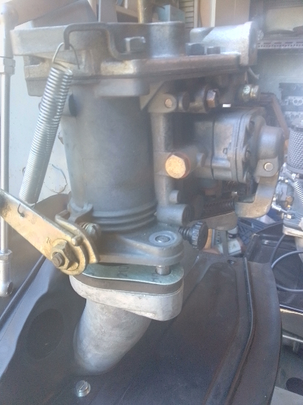
AT RIGHT: Unfortunately, the right-hand Solex 40PII was damaged through a process called "cold flow". This is where someone overtorques a fastener, and the casting distorts under the too-extreme load. In this instance, the mounting holes were closed up under the pressure of having been over-torqued as can be seen in the several images here.
BELOW: NONE of the four holes would permit this drill bit, which is significantly smaller than the original bores, to pass through them! REMARKABLE, especially when you see just how much smaller the bit is from the original bores.
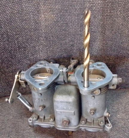
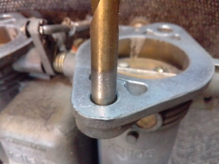
And now, the drum-roll, just how much smaller IS that drill bit, anyway?
As we can see at right, "alot!" would be accurate. ... To put a number on it, the constriction point was nearly 2mm smaller than the main bore! The solution, obviously, was to drill out these bores to be at least bigger than the M8 studs that have to go through them! And this was, of course, done.
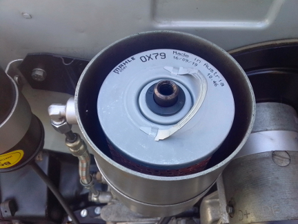 The
oil filter was replaced and as both the inlet and outlet lines to and from the
bypass filter were feeling stiff, as they do when they are about to start leaking,
we decided to replace them, too.
The
oil filter was replaced and as both the inlet and outlet lines to and from the
bypass filter were feeling stiff, as they do when they are about to start leaking,
we decided to replace them, too.
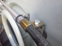
AT RIGHT: We drained the oil from the bypass filter canister and installed a new OEM filter and both inlet and outlet lines.
When the valve gear was installed and preliminary valve adjustment performed, we had left the engine rotated to TDC of cylinder 1 at the transition from compression to power strokes. So, we checked the point gap (it was perfect) and installed the distributor drive gear followed by the distributor. We then did a static time of the ignition so it would start readily. At this point we noticed that the distributor does not return fully to zero! The test is simple: Rotate fully clockwise and it should return to fully counter-clockwise. If it doesn't, the springs aren't returning it to the full idle (fully retarded) position for whatever reason. However, we were / are not tasked with fixing that, and since it won't negatively impact running-in the engine, we proceeded, continuing next with installing the new spark plug wires and distributor cap.
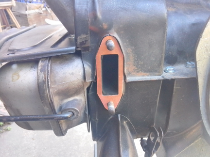
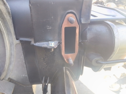
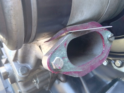
Because the asbestos-free exhaust gaskets we get today don't have the mechanical strength to do the job, we use copper coated with a sealing compound. These are laser cut to the same size as the standard (late type) exhaust gaskets, but still require hand drimming to clear the sheet metal since the ones in the gasket set are actually a bit too large. (We, 356 Coachworks, make these gaskets ourselves, and for our next batch, we're going to make them just a little bit smaller to hopefully eliminate the need for hand trimming!)
BELOW, LEFT & RIGHT: Here we see the copper exhaust gaskets, required because the modern asbestos-free ones just don't have the mechanical strength to do the job. (Note that the original asbestos type were impregnated with wire for good mechanical strength.)
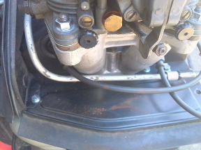
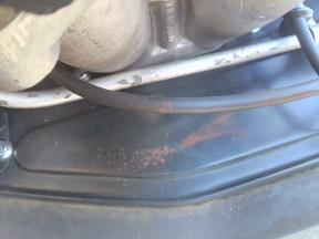
When you know how, it's not hard, so we spent a few moments and "straightened" the metal fuel line so it's not all bent out of shape as it was before.
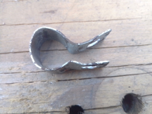
BELOW: There was also a bit of difficulty in securing the fuel line up at the top center of the fan shroud. This was due to a retaining strap that had been bent up over its nearly 58 year service life. ...It just wasn't worth the time to try and straighten it, so it was just replaced. Oh, and the fan belt was badly cracked all a around - it's amazing it hadn't failed already. These cracks are, like the stiff oil hoses to and from the oil filter, signs of long term heat, and we believe this is likely because the engine is missing the radiative heat deflector that goes between the oil pump and muffler and also helps scoop up air from underneath and cool the rear of the engine bay by removing heat collecting above the muffler as the automobile moves forward.
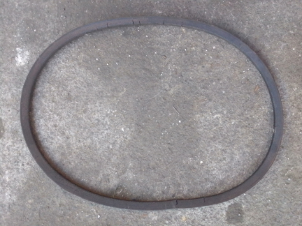
BELOW LEFT & RIGHT: After years of the generator stand to T-6 type filler / breather gasket NOT being provided, we were delighted to see it now in the modern gasket sets. Unfortunately, it's the wrong size on the outside, as we discovered after installing it. So, we trimmed it back with a razor, as seen here. (Note on the lower edge where the sealant is still on the gasket; that area all has to be cut off!) And, of course, we stock the original fan belts - the new one is the exact same type as the old one! Note the pulley is now the correct four-hole unit!
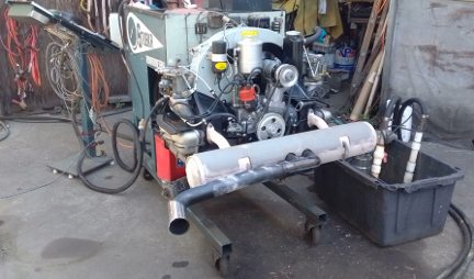
At right about this point, there were multiple of us in the workshop so an ideal time to shuffle a 912 engine off the dynamometer and this one onto it, and clear the running-space where the dynamometer usually sits when in service, and along the way the flywheel and clutch had to be installed. Unfortunately, we were so distracted, we didn't get any images of the setting of flywheel end-play, clutch installation, etc. But once the engine was on the dyno, as can be seen below, we promptly installed the loaner muffler.
At this point, it's technically complete, so we're going to transition here to the run-in section.
 Run-In
To get the engine ready to run, we installed an oil pressure sending unit that can operate both a gauge and an "idiot light", then hooked up all the wires, the throttle linkage, added engine oil, etc, etc, etc, and got the engine ready to run.
AT RIGHT: The dynamometer has two VDO brand oil pressure gauges, so we have several sending units on hand that work quite nicely on 356, 912, or 911 engines, as the one seen here. Note also that, in contrast, though VDO brand, our temperature gauge doesn't match this sender, so we didn't hook it up.
Before any fuel could hit the system - which also means "before the engine is spun by the starter" - we checked the Main Jets and found them to be 115. These were the original size recommended for sea level, but that was with a smaller engine (82.5mm bore vs 86mm), and that was with the higher-quality fuels of yesteryear. Today, especially here in California, our fuel is diluted, it's more dense, and has less energy and thereby engines require more of it. This means the float rises and therefore cuts off the fuel earlier, and therefore makes the float levels too low. (The measures for pollution are intentionally manipulated by the fossil fuel industry to require MORE fuel as the measures are based on unit volume rather than either net energy content, horsepower-hour, passenger-mile, or other qualitative measure.) ...So, we know from experience that they should be bigger. We tried 127.5 as a first pass. This turned out to be very close, but we'll be trying 125 later, and maybe 122.5 if we have them in stock.
In any event, this odd powder came out of carburetor when we pulled jet #3:
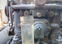
We ignored the powder and instead installed our new jet size and also a Solex float-bowl sight-glass, then focused on throttle linkage.
We had left the throttle linkage alone from the previous installation but found that, based on the down-link rod adjustments, it's very likely this engine did not previously have all of full-throttle, though that's only a guess. However, we're also fairly sure it had a rubbing throttle linkage rod as our dyno brings the throttle through the forward closing panel in the stock location and we found it rubbing, and that led to discovery of the forward bellcrank (flywheel side of the fan shroud) was bent a little, so we corrected it - this should be double-checked in the vehicle where this engine lives as it's possible that the wrong bellcrank on the transaxle would change the location the throttle rod comes through and that may explain why it was bent.
Now that it was just about runnable, the last step was to gain oil pressure. This is done without spark plugs so the engine doesn't create compression and so it spins very fast and oil pressure comes right up, and while we're doing that, we're also filling the carburetors with fuel! Nice! That done, we installed the plugs (always new in a new engine!) and started it up to checked for leaks.
It started right up on the first moment it got fuel and ignition and purred reasonably well. And, we didn't find any leaks, either. We then realized we'd neglected the Dynamometer's battery, so we set it to charging and went off to do other things. We came back to realize we'd left the master switch on on the dyno, so the hour we were charging the battery we were also ticking off an hour of dyno time that we shouldn't have. Oops! Note made in log-book and we proceeded to start it up and tune the carburetors and check the ignition timing in preparations for the actual run-in.
When we got back to it, the idle was set pretty well with only one lean-pop from the idle system, and the left-to-right balance was also very good as was. So, we set the linkages to match, right vs left, and then checked the float levels. Both sides were low and corrected, of course.
BELOW, ALL FOUR: As predicted when we saw the main jets, these carbs were not set up for modern California fuels and, therefore the floats ride too high and shut off the fuel too soon, leaving the float levels low, as can be seen here, along with the corrected levels.
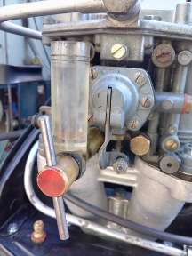
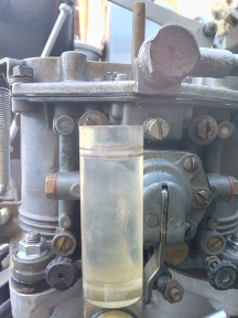
 Following
this, we had observed a bit of fuel down below, but ignored it for now, thinking
it from the sight-glass, which doesn't seal as well as a real main jet does,
and proceeded to check the accelerator pump volumes.
Following
this, we had observed a bit of fuel down below, but ignored it for now, thinking
it from the sight-glass, which doesn't seal as well as a real main jet does,
and proceeded to check the accelerator pump volumes.
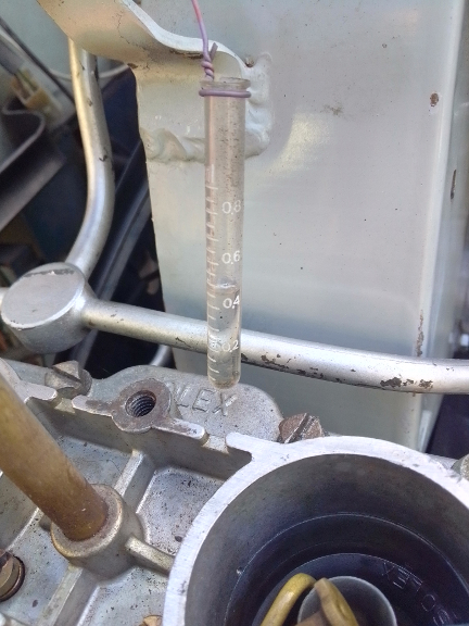
AT RIGHT: Taking a photo of this was harder than it might seem as the contrast of the background is a problem as is paralax and distortion caused by the glass itself showing the fuel level a little differently depending on the paralax - viewing angle. However, here we can see the injection quantity (two pumps) is above 0.4 ml and below 0.5 ml, which is perfect for the present conditions.
However, after the injection quantity check, there was new, fresh fuel present, as seen below:
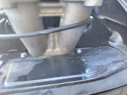
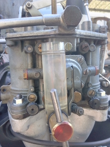
At first it wasn't clear where it was coming from. After trying the basic things, such as snugging the accelerator pump screws, and gently tightening nearby features of the carb, we finally saw a drip comming from the accelerator pump itself, and managed to get a photo of it.
AT RIGHT: A drip can be seen forming on the lower edge of the accelerator pump. While we weren't explicitly charged with doing carburetor repairs, we can't run it in with a fuel leak - too much risk!
As we are professionals, we both know what to do and have the requisite parts on hand.
BELOW: At left, the old accelerator pump diaphragms and at right, the new ones. What we find remarkable here is that the tear in one of the pump diaphragms is so clearly visible! Normally, it's generally not known where the diaphragm is leaking from, only that it leaks!
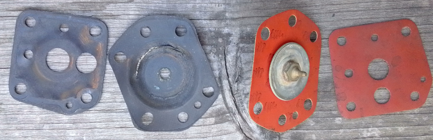
Logic suggests the other one would be as bad, so we asked our customer and even though we weren't originally tasked with this, they approved our replacing the other side's accelerator pump diaphragms as well..
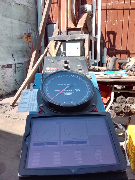
BELOW: So, it's FINALLY time to actually do the run-in! So, we had to clear out the space and move the test stand to this spot.
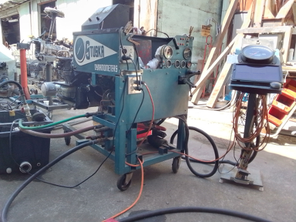
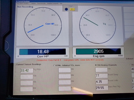
The black hose foreground left is the water feed hose. The amount of water coming through this hose is governed by the load control system, starting with a box that's hard to see in the image at left because it's in sunlight, directly above the dial on the control stand. This box has an RPM signal and an input from the operator and gives a signal indicating more, less, or the same amount of water to another computerized box that's mounted to the radiator stand. The red hose at left, is the output of hot water from the engine brake to the catch basin. The green hose is the brake's vent to atmosphere - it may spit water now and then. The two black hoses on the right edge of the image at right are the water return hoses coming from a sump pump that's under the control of the operator via a switched outlet on the control side ("front") of the dyno. On the control stand (facing the viewer on the right edge of left image and, facing away on the left edge of the right image), there's also a weather station, and a display computer that we'll see an image of below.
More about the dynamometer can be found here.
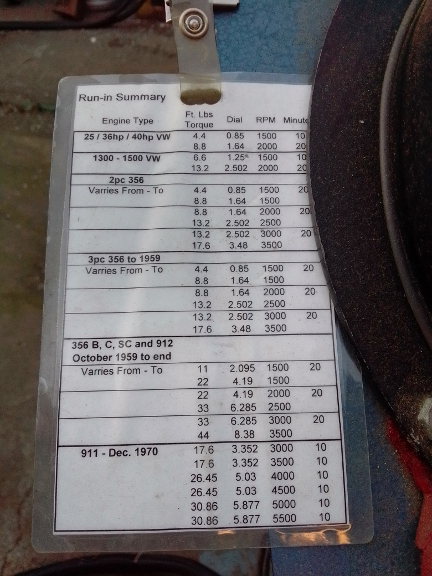
We follow the directions Porsche thoughtfully provided in the workshop manuals. The proper procedure for this engine type is documented in the later 356 B/C Workshop Manual, operations 52 EN, 53 EN, and 54 EN, pages E83 and E84. And, yes, we have a cheat-sheet we use so we don't have to pull the manuals out every time we run-in an engine - it's seen below.
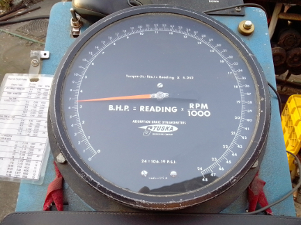
All set now, here's the control stand - it has everything except the throttle...
Here, we're transitioning from the second to third 20 minute period - note that the RPM, and hence torque (and HP) waiver up and down some, and there's no such thing as a precision like "exactly this RPM" ... We would be gently adjusting the throttle to get the RPM just where we want it except that we were busy taking photographs, so it's just close:
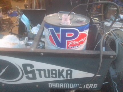
During the run-in a few things happened. Most notably, the generator started making noise which we determined is likely a bearing that's failing. We stopped to ensure the belt tension is loose and it is / was. And, we ran out of gasoline! So, we completed the run-in with a bit of racing fuel we just happen to have on hand. (Gee, I wonder why that might be?!)
 And,
after it was all done, we're not done yet, of course, as we do a final valve
adjustment, etc.
And,
after it was all done, we're not done yet, of course, as we do a final valve
adjustment, etc.
Meanwhile, we were left with this surprise. Yes, it's actually a leak from the left valve cover! Remarkable that the oil went UP, isn't it?! There's no drip to the ground. It's a mild leak but we fixed it with a new gasket. (The former one looked new but was installed with a sealant that didn't hold - we used Permatex Aviation-Grade as we know it holds up.)
And, we have some followup with our customer over whether they want us to handle the left-hand carburetor's accelerator pump diaphragm or not, etc...
...We subsequently got the approval to replace the left hand accelerator pump diaphragms, so we did. And, as can be seen in the images below, we were also considering changing the main jets, too. However, in conversation with our client, we decided to leave the engine with 127.5 main jets for a final determination left to them.
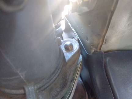
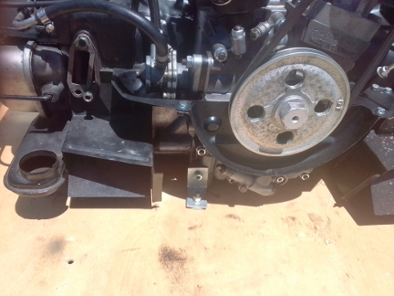
BELOW, LEFT & RIGHT: Above, near the top, we commented we liked and use ourselves the former strategy used on this engine of mounting the engine to the crate via the main transaxle to engine studs, and how we don't do the pulley side the same way. Well, here we show our work completed. And yes, we used the same brackets they did, though we added a second bolt for each angle-bracket to the crate base, and we also added a second nut on the studs, so that there are two nuts are backed together with the bracket in the middle. On the pulley side, we use a much simpler and probably more stable solution of simply using a relatively thin, but also relatively small / short (and therefore strong) angle bracket, using the lower left third-piece stud. Now, our angle bracket was a little short, so we put large diameter washers beneath, so it's a good fit. ... Cheap, and very solid!
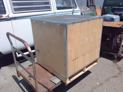
BELOW, LEFT & RIGHT: Here we see the engine from a little further back so we can see just what was shipped.
BELOW, LEFT & RIGHT: Here we show the left over space - there is just enough room to fit the stock muffler, though the engine needs to be a little closer to the crate wall on the flywheel side - those few inches left over need to go to the rear, but there is room!
BELOW: Crated, waiting for pickup from a shipping company.
Because some people are keeping logs of VIN and engine numbers and then purport to tell people what someone else has, out of respect and concern for a buyer's privacy, exact VIN and engine number data are not published here.