Copyright © 2007 - 2025, Coachworks For contact data Click Here.
Copyright © 2007 - 2025
Copyright © 2007 - 2025,
Coachworks For contact data
Click Here.
![]()
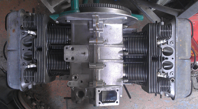
This engine, in long-block form, is ready for pickup or delivery today, and may be purchased complete, ready to install, with only a few days delay.
This 1963 356 SC engine was factory rebuilt in 1968 and period correct for such a rebuild (excepting larger cylinders) and has just undergone a complete overhaul, and is fully balanced for smooth running, long life, and a few more HP.
The engine is effectively an SC as envisioned by Porsche as if it had been manufactured new in 1968 instead of '63. It has all the best engineering of a 912 engine in an SC package. So, of course it has the late-type oil pump, late rockers, late heads (minus black anodizing), etc. During this rebuild it was fitted with 86mm pistons and "durrel" cylinders provided by the late Duane Spencer.
The engine has had very little service since it was rebuilt by Porsche, however, in spite of this, it has undergone a thorough rebuild. Every detail about the engine has been attended to, as outlined below; nothing was ignored.
Here it is as a long-block, ready for pickup or delivery (above).
 I
received this engine from a close friend in the Torence / Palos Verdes area
of the Los Angeles basin, who has been a lifelong air-cooled enthusiast in that
area, and he told me the history of this engine. But, it was a long story -
too long maybe! - so what follows is an abbreviated summary, as best I can.
I
received this engine from a close friend in the Torence / Palos Verdes area
of the Los Angeles basin, who has been a lifelong air-cooled enthusiast in that
area, and he told me the history of this engine. But, it was a long story -
too long maybe! - so what follows is an abbreviated summary, as best I can.
A high-school friend of his was the original owner of the vehicle this engine came from. In 1967 or '68, when the car was 4 or 5 years old, the engine needed overhaul and the gentleman elected to have Porsche do the work, so it was sent back to Germany. Apparently, it took a long time and when it came back, in his excitement, he drove the vehicle a bit wildly and stuffed it into the back of a truck. With the car gone, my friend helped guide the engine to another friend of his, Parnelli Jones (famous in air-cooled 1/4 mile, land-speed, and other racing venues in the LA area), who put the engine in a "dune buggy" based on a shortened VW chassis. However, apparently some kids broke in and the vehicle got vandalized shortly thereafter while in the shop of "The Engine Compartment" - predecessor to the well known firm "West Coast Metric" (think Lorn Pearson). As the vehicle was non-operable, and as the engine was exposed with easy access, various parts were taken off of it for other projects, until it wasn't much more than a long-block. And there the engine sat, in the buggy in Mr. Jones race shop, until Mr. Jones was old enough to retire and the shop shut down. During that process, the engine traded hands to a guy named Kevin, one of the people helping close the shop, who conveyed it to my friend from whom I got it.
There is evidence that the engine was disassembled since Porsche put it together, namely the use of what looks like red Permatex "Gasket Seal" as case sealant (the original was Permatex "Form-A-Gasket") - you'll see remnants of it in the images of the case. We presume it was Mr. Jones' work, but this remains speculation. My friend is trying to reach Parnelli Jones to confirm. Whoever took it apart had to be either Mr. Jones or someone he hired to do the work, but as he was a fairly famous racer, it's entirely plausible he did this himself. But, one would have to wonder what he might have done in there as it all appeared stock without any modification - maybe he just wanted to check it out?
 So,
following rebuild by Porsche, the engine served only a brief time in its original
SC vehicle before being transferred to the buggy, where it only went on a couple
of outings some 40ish years ago, and hasn't been run since (though I intend
to test-run it if I build it out as a complete engine). I didn't run it when
I bought it, thinking that unwise, and besides, it was incomplete. Instead,
I let it sit for years and years "borrowed" a few parts off of it,
too, and slowly dismantled it before deciding to put it back together in the
late summer of 2012.
So,
following rebuild by Porsche, the engine served only a brief time in its original
SC vehicle before being transferred to the buggy, where it only went on a couple
of outings some 40ish years ago, and hasn't been run since (though I intend
to test-run it if I build it out as a complete engine). I didn't run it when
I bought it, thinking that unwise, and besides, it was incomplete. Instead,
I let it sit for years and years "borrowed" a few parts off of it,
too, and slowly dismantled it before deciding to put it back together in the
late summer of 2012.
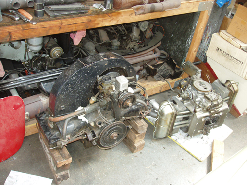
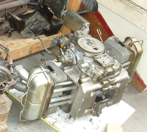
I don't appear to have taken photos of the engine as I received it, but here it is, above and below right, shortly thereafter as I was looking for space to put it on the engine-shelf. I've provided a close-up so you can see it better.
Note the yellow writing on the distributor - that was just something to keep the distributor drive gear from moving and damaging the bronze gear on the crankshaft should the engine be rotated. But what gives me a lot of confidence in the story of this engine's history, aside from the integrity of my friend, are several interesting facts:
Once the decision was made to put this engine back into service, the first thing to do was disassemble it, of course! This work went pretty quickly, maybe an hour, in large part because the engine had lost pieces in support of other 356 efforts over the past 40 years or so and wasn't complete. Disassembly also went quickly because I used a special crankcase parting tool that ends forever any need to bang, tap or pry the case halves, so they remain pristine - and it's very fast. Unfortunately for documentary purposes, work went so quickly that by the time I thought to take any photos, it was already over!
 Crankcase
Preparation
Crankcase
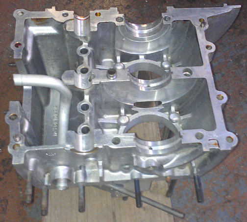
Preparation All I had to do was wash it, give it a visual inspection, torque it up, measure the bearing bores, and measure the cylinder spigots (on each side) to ensure they're all in the same plane with their neighbor (and not angled or of differing height). These checks revealed no flaws. The crankcase is in fantastic condition.
This case has never been align-bored and presently measures on the small (tight) side of standard, so much so, in fact, that it's borderline TOO unused! To be specific, for those numbers nerds out there, every bearing bore (1 through 3) measures between 60.230 and 60.235 - any tighter and it would need work to be able to be used! What this means is that this crankcase still, right now, has the greatest potential for the longest life of any Porsche 356 engine ever made.
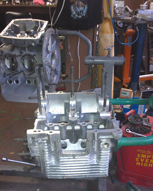
At right you can see the left crankcase half awaiting assembly - look how it just gleams! (Behind it is another SC undergoing a similar renovation - it just happens to have also started life in 1963 - and in the distance, right, there's an SC destined for a "D". Odd that there are three SCs going together at one time!)
I happen to like to provide bare crankcase images because it really shows the foundation of it all. So, here's one of the right case half. Again, as cited above, I can't recall another engine that's ever been in service that's as clean as this example - I really think it has close to zero miles on it, but you can judge for yourself...
 Even
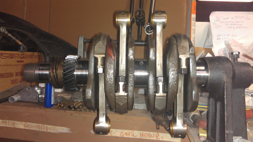
though people lump the SC and 912 crankshafts into one grouping because they
are functionally interchangeable, this crankshaft is actually a 912 unit - you
can tell because the long "cheek" that transitions from rod to rod
without a bearing in between is parallel (as can be seen in this image, below
right) from approximately rod center to rod center on the 912 version, and has
a much longer taper on the SC version.
Even
though people lump the SC and 912 crankshafts into one grouping because they
are functionally interchangeable, this crankshaft is actually a 912 unit - you
can tell because the long "cheek" that transitions from rod to rod
without a bearing in between is parallel (as can be seen in this image, below
right) from approximately rod center to rod center on the 912 version, and has
a much longer taper on the SC version.
The original rods were so "new", their patina included ink stamps that I found irresistible for another project, so I had to replace them with another late-type set. Of course, they're fully rebuilt! I rebuild rods in batches - it's easier / faster / cheaper that way as it keeps setup time to a minimum.
 For
me, "rebuilding the rods" means to:
For
me, "rebuilding the rods" means to:
This is all standard work so there aren't any photos of them in-process. But here's a batch (above right) from earlier this year. The set in this engine is either one of the six sets in this batch, or is from a preceding batch.
As usual, I mounted the crankshaft up on the ole crankshaft stand and mounted up the rods. The red mark indicates that I also magnifluxed the crankshaft to check for cracks and then rotationally balanced it - I had forgotten about that!
 Crankcase
Assembly
Crankcase
AssemblyOne of the first things one does is check the bearing fit, but as a standard, untouched crankcase, that went quickly. Out of prudence, modern production bearings from Stoddard have been fitted. They're the heavy type with little crush and I had some trepidation that their lack of "crush" with the tight case bore would mean that the bearing would keep the case from clamping fully, but it seems to have worked out OK.
Next, one sets the crank in place and checks the fit of the camshaft. The gear is a zero and seemed a little loose to me, so I tried five different gears to obtain a better fit but nothing worked better than the original gear, so I put it back on!
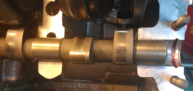
The camshaft is worthy of some note. It's a wide-lobe 912, known as the R200, and is the "replacement" camshaft Porsche chose to supersede the earlier design. What's notable is that this camshaft is "like new" in that it's a parkerized cam, as all stock cams were, and the coating from the parkerization process (a black film that actually penetrates the surface a few molecules) hasn't even been run-in yet! Generally, the run-in process takes a thousand miles or two, so that further supports that this engine has virtually zero time on it. In addition, the drive slot for the oil pump has virtually no wear, either.
You can see these features in the following images, below right.
 At
right, both the identification marks on the cam and the wear into the parkerization
are evident. Note the pattern on one side - this lobe shape is slanted to help
the lifter rotate.
At
right, both the identification marks on the cam and the wear into the parkerization
are evident. Note the pattern on one side - this lobe shape is slanted to help
the lifter rotate.
In the next image below, you can see the end of the timing gear and both the oil pump drive slot and the identification marks for the cam. Note the "200.5". And yes, it was made by Sachs.
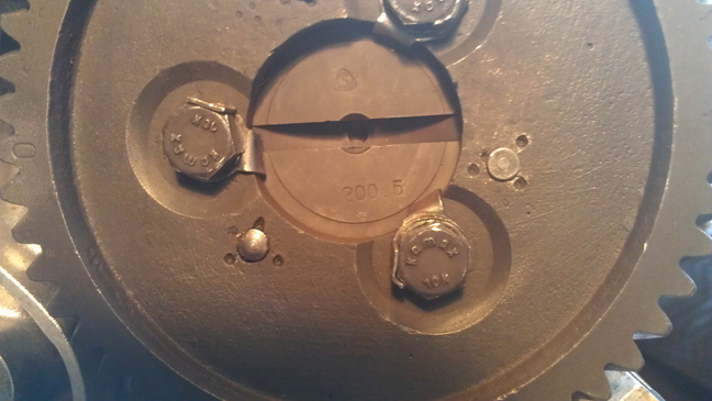
Parkerizing is a hardening process which eliminates any "need" to over-rev the engine to work-harden the cam lobes. (If anyone ever tells you you must rev your freshly rebuilt engine to high-rpm in order to work-harden the camshaft lobes, you've chosen the wrong parts vendor / cam grinder! This should never be required! If you're racing, that's one thing, but most of us can afford the normal, gentle run-in process that results in a long-lived engine...)
 Also
worth pointing out here that I refaced the cam followers, just to be sure they
wear-in correctly, though it was probably unnecessary, and you can see them
as the case halve go together...
Also
worth pointing out here that I refaced the cam followers, just to be sure they
wear-in correctly, though it was probably unnecessary, and you can see them
as the case halve go together...
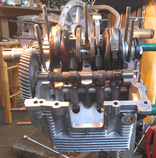
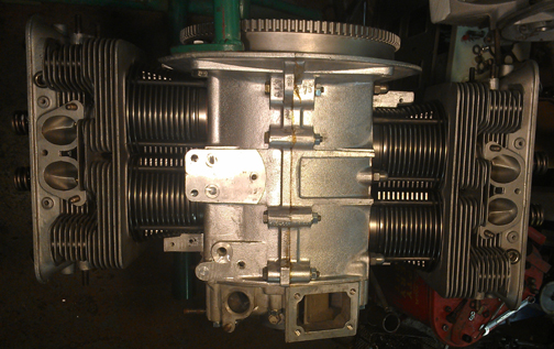
Now, time to put the case halves together! Prep-work done correctly, this goes easily and quickly and the story is best told in images:
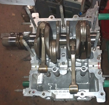
In this first one, at right, though the lighting is poor, you can see all the features previously described coming together - the balanced 912 crank, the rebuilt rods, the parkerization, the refaced lifters, and that red case sealant (cam end-plug)!
Next, bolt it up!
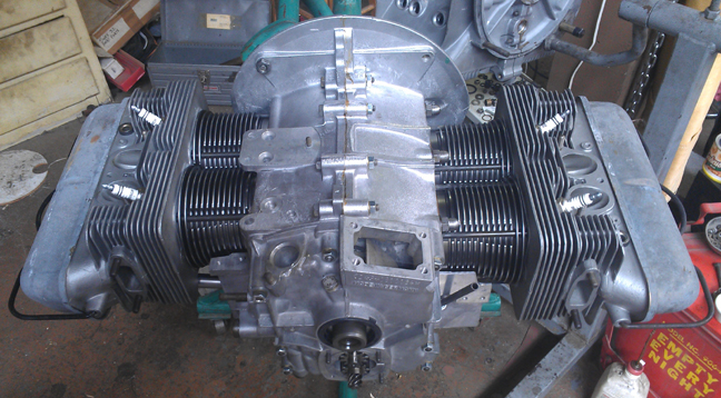
That goes rather quickly, the timing cover goes on, and here we have it as a "bottom end:"
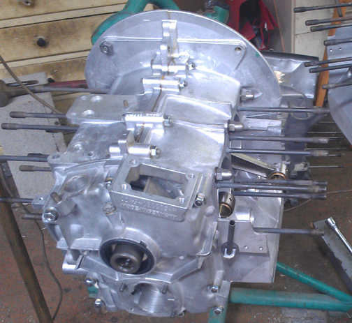
I love the way this engine gleams so much it positively glows!
And yes, if you're sharp-eyed, that is a two-piece case Porsche "pre-A" engine, awaiting its turn on an engine stand! (There are only eight, but they're all in service!)
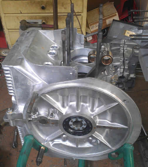
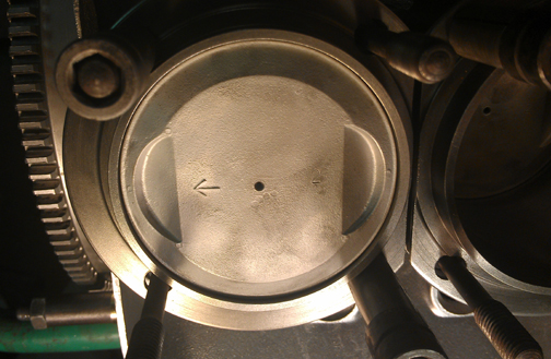
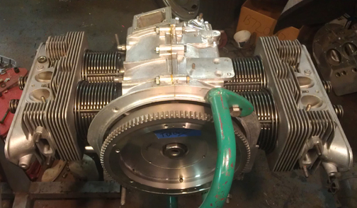
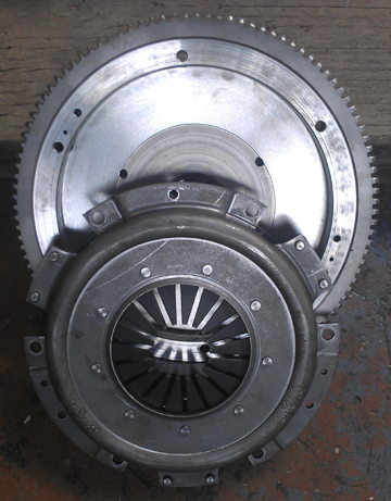 It's
necessary to rotate the engine while fitting the Pistons and Cylinders in preparation
for mounting the heads, so the flywheel was mounted up. Here it is, ready to
go, mated to a new pressure plate.
It's
necessary to rotate the engine while fitting the Pistons and Cylinders in preparation
for mounting the heads, so the flywheel was mounted up. Here it is, ready to
go, mated to a new pressure plate.
The heads looked really great (left pair in image at right), and are probably perfect - except for the fact that the springs have been in compression for something like 40 years and have, no doubt, relaxed some tension.
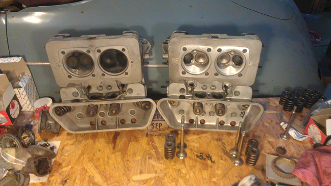 I
would have perhaps just replaced the springs, but because of the new, large
bore (86mm) pistons and cylinders, the combustion chamber must be reshaped
to make sure there's no problem with the piston hitting the head. This is called
a "conical cut" because it's a machine step that essentially
cuts a cone that's executed at the same angle as the bevel of the crown of the
piston. So, to use these P&Cs, the head would have to be machined.
I
would have perhaps just replaced the springs, but because of the new, large
bore (86mm) pistons and cylinders, the combustion chamber must be reshaped
to make sure there's no problem with the piston hitting the head. This is called
a "conical cut" because it's a machine step that essentially
cuts a cone that's executed at the same angle as the bevel of the crown of the
piston. So, to use these P&Cs, the head would have to be machined.
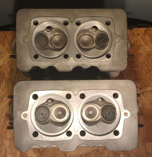
Instead, I just happened to have a beautiful set of heads ready to go and chose them. Firstly, these heads have never been cracked as 912 heads (and C / SC heads) are prone to cracking between the spark plug bore, intake seat bore, or exhaust seat bore - or any combination thereof - when overheated. Secondly, these heads have have new guides, and refaced valve seats. Thirdly, these are really the same heads, and NOT the awful, even more crack prone (without overheating!) air-injection 912 heads - or the even later ones where the casting has fin-loss at the place where the air injection formerly would have been. Finally, these heads have been carefully gone through to repair or replace any damaged studs or threaded holes, as necessary.
 Fitted
to these heads are great valves. They're originals, not aftermarket replacement
which are all you can get new today. Further, and vitally, the exhaust valves
ARE the sodium filled type, which haven't been available new for some years
now. Of course, the valves have been checked for length (stretching makes them
unworthy), polished, and refaced, so they're effectively perfect.
Fitted
to these heads are great valves. They're originals, not aftermarket replacement
which are all you can get new today. Further, and vitally, the exhaust valves
ARE the sodium filled type, which haven't been available new for some years
now. Of course, the valves have been checked for length (stretching makes them
unworthy), polished, and refaced, so they're effectively perfect.
New springs, of course, carefully selected.
Previously, we went through a large batch of about 40 new springs and they were grouped by strength. We match up slightly stiffer springs with the heavier valves (intakes are about 2% heavier than exhausts), so they're very close sets, matched up, so all the valves tend to float at the same time. ...Of course, each valve and retainer are position-specific through the shimming process...
After the valves are fitted, the combustion chambers are measured with a burrette. Both heads work out to 58.6ml.
 Pistons
and Cylinders
Pistons
and CylindersWhile the original SC / 912 pistons and cylinders were still fitted to the engine, the emphasis these days seems to be for more horsepower, and "there's no replacement for displacement." So, in keeping with the idea of a quality set, I selected these "Durrels" I got from the late Duane Spencer a couple of years ago - I had bought a few sets and this seems like a fine time for a larger bore. They're 86mm. They're beautiful.
New parts are not exempt from careful checking!
We always check the match pistons to cylinders and match piston weights as a set, and provide any remedial action to correct any errors before installation. For example, by shuffling around the piston pins among the pistons, one can usually improve the matching of piston weights. This set naturally balanced (without removing material) to within 0.3 grams - the official specification is ten grams (10g) - with three of them at the exact same weight (458.5g) and one a little lighter.
For many shops, from this point, installation goes very quickly, but we think this is where one needs to take one's time! The key reason one needs to take time here is that there are production tolerances on every part in an engine, and while a set of parts may look identical, there's often subtle variation between members of a set, and there are sometimes significant errors in production that weren't caught by the manufacturer's quality control processes. These errors can "stack up" and cause problems if not discovered and corrected.
 Here's
our process: Two of these steps require special tools most shops don't
have.
Here's
our process: Two of these steps require special tools most shops don't
have.
 We
like to carefully measure everything and then mix-and-match the parts for superior
fit. We have also discovered significant manufacturing errors with this process
which would likely have gone unnoticed without these measures. It is remarkably
easy, for example, to overlook the circumstance of the crankshaft bore not in
the true center of the crankcase, angled on the horizontal left or right of
center, or not on the same horizontal plane at all. Yet examples of errors like
these are not as uncommon as we would like.
We
like to carefully measure everything and then mix-and-match the parts for superior
fit. We have also discovered significant manufacturing errors with this process
which would likely have gone unnoticed without these measures. It is remarkably
easy, for example, to overlook the circumstance of the crankshaft bore not in
the true center of the crankcase, angled on the horizontal left or right of
center, or not on the same horizontal plane at all. Yet examples of errors like
these are not as uncommon as we would like.
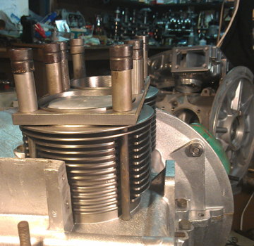
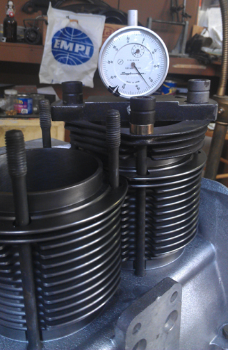
Here you can see them being fitted for height comparison check - this is done to ensure that there are no difference between the cylinder heights that the head itself "sees." The book value for tolerated error is 0.1mm (four thousandths of an inch), but in this case, there was no measurable difference between one pair, and less than 0.0015" (less than one point five thousandths of an inch, or 0.0275 mm) for the other. I suspect that these cylinders have better quality control - in particular, more consistent heights - than the more familiar iron cylinders, though I haven't yet had enough sampling size to feel sure that's true. At least these and another set I installed all matched exactly.
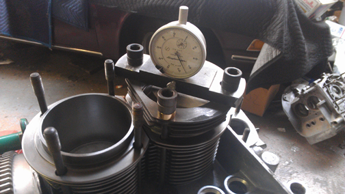
The next thing we do is something nobody else does (that we know of) in the engine building process, and that is to measure the height the piston crown comes above the plane of the top of the cylinder. I call this the CAC, or "Crown Above Cylinder." This value is important because, firstly, it can reveal deeper problems, and because it helps us get the compression ratio equal in all four cylinders.
Here are some of the deeper problems that can be discovered through a CAC check:
In order to do this for these engines, you have to have special tools. Here, you can see them in action on this engine in the two images above.
Even if you can't read the needle in these images, you can tell that these are cylinders 2 (lower), and 3 (upper), and you can see that the needles are in virtually the same exact spot! That's what we want to see! The distance between the smallest tick marks is one hundredth of a mm, or 0.0004", and you can discern to perhaps a tenth of that! So, this is a very accurate measure, performed while the cylinder is under torque, so any shims are squished flat, etc.
The accuracy is so good, that if you take the time to swap parts around, you can accurately determine discrepancies in the manufacture of the various parts! But, we ARE splitting hairs here! However, a benefit to both engine builder and customer is that the ability to move parts around for better fit means that perfection is more easily achieved, and the more equal the HP production of each cylinder, the smoother the engine will run, and the more HP the engine will produce overall.
Because this process includes the entire assembly, torqued as in service, and measures the height each piston protrudes out of its cylinder, all errors in connecting rod lengths, cylinder heights, crankcase spigots depths (cylinder bore deck), piston connecting pin heights, and shim thickness' are accounted for in the measurement results. There is no superior method.
 At
this point the engine is ready for its cylinder heads, and this work went very
quickly - as it should! - as all the prep work was already done.
At
this point the engine is ready for its cylinder heads, and this work went very
quickly - as it should! - as all the prep work was already done.
Prepare the head "bolts" and washers, prepare the pushrod tubes, prepare the lower cylinder air deflection plates and their wire retainers, and get the torque wrenches set, and bolt on those heads!
My pattern is to mount one head, torque it to 7 ft lbs (as per the manual), then mount the other head the same way, and then alternate between the heads with an ever-increasing torque up to the final torque value, then repeat the final value until the fasteners no longer turn when torque is applied.
I installed powder-coated lower cylinder air deflector plates, and tried to get an image of them, but you really can't tell. Oh well. Here's one such image anyway (above right).
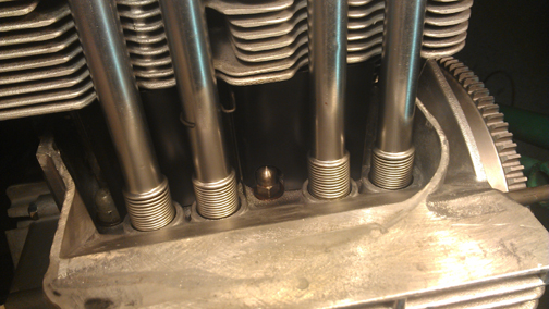
I took a lot more images, but it was becoming dark in the workshop (which is well lit via skylights during the day), and the images were very poor due to contrast problems. But this one shows the left side (3 & 4), ready for its head.
And here below, a couple more:
OK, mount the valve gear, adjust the valves and pop on the valve covers.
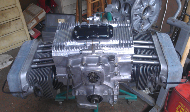
Then fit the oil drain plug, and sump screen and plate. Of some small note is that all the sump studs are original and in fine condition. I used new cap-nuts to protect the studs into the future.
Then, fit the two oil control pistons. I used new springs because I figured the old ones had been compressed for some 40 years!
Can't forget the oil pump! In the images below, the cover for it is still in the parts washer - it should be gleaming just as much as the rest of the engine!
And now here it is as the longblock, ready for pickup or delivery (minus pump cover!):
NOTE: If this engine is sold as a long-block... One should NOT install the distributor drive gear without also installing a distributor because if anyone rotates the engine backwards, it will push the drive gear up where it can damage the bronze drive gear! Therefore, the distributor drive is NOT mounted until the last reasonable moment!
Because some people are keeping logs of VIN and engine numbers and then purport to tell people what someone else has, out of respect and concern for a buyer's privacy, exact VIN and engine number data are not published here.