Copyright © 2007 - 2025, Coachworks For contact data Click Here.
Copyright © 2007 - 2025
Copyright © 2007 - 2025,
Coachworks For contact data
Click Here.
![]()
This engine, in long-block form, is ready for pickup or delivery today. This engine is also available as a complete Turn-Key engine, optionally Run-In on our Stuska water-brake engine dynamometer as per Porsche factory specifications as outlined in the Workshop Manual, operations 52 EN, 53 EN, and 54 EN, pages E83 and E84. You can see this being performed on another of our engines here - see the second image down.
SPECIAL NOTICE
This web page is still under construction!
This disclaimer will be removed when all the images and text work has been completed.
Meanwhile, the contents are most likely accurate, just incomplete.
Links lower down on this page:
This December 1963 356 C engine is "numbers matching" with big-bore pistons and cylinders, and has just undergone a complete overhaul, and is fully balanced for smooth running, long life, and a few more HP.
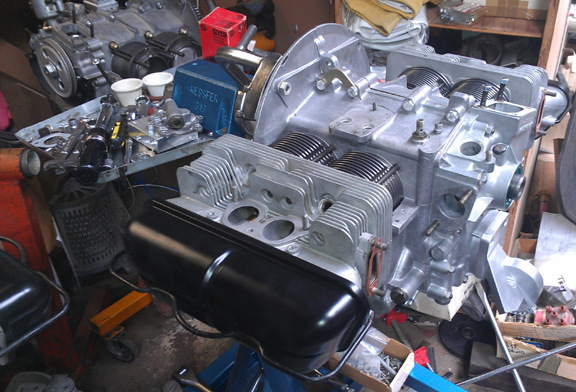
The engine is a C so it is effectively the best combination of durability and performance of any 356 engine ever made. One can think of the C as a slightly de-tuned SC, though in this instance, it's fitted with an SC crankshaft (counterweighted), and the SC's camshaft. So, it has all the best engineering ever built into a 356 pushrod engine. So, of course it has the late-type oil pump, late rockers, etc. During this rebuild it was fitted with big-bore pistons and cylinders (86mm).
Every detail about the engine has been attended to, as outlined below; nothing was ignored.
This was a "spare" engine to an SC automobile, and was rebuilt by Bob Sturm in 1986 using many SC parts. Since then it had about 30,000 miles put on it before the rebuild depicted here. Some of the "upgrades" have been kept, such as the SC crankshaft and camshaft, but the stock pistons and cylinders have been replaced with the ubiquitos "big bore", for a bit more power.
 Crankcase
Preparation
Crankcase
Preparation First, the case was carefully cleaned.
Inspection revealed no flaws. Measurement of the bore shows it remains standard, with the original "crush" on the main bearings.
I then measured the cylinder spigots (on each side) to ensure they're all in the same plane with their neighbor (and not angled or of differing height) - they're perfect. And then I took the two halves apart again and checked carefully for any cracks, damaged threads, etc. These checks revealed no flaws.
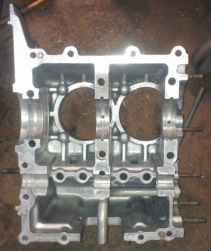
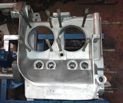
AT RIGHT: The right case half, cleaned, inspected, and read. Note how it gleams!
BELOW: The casting date (week over year) of the left case half.
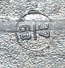
The surface at the joining plane with its other half is very close to absolute perfection.
Now, the other side. Down below, during assembly, there are images showing the inside of the left half. And since I don't usually take images of the outside of the case, this time it was just so perfect, you have to see it! The outside of the right half is just as nice.
BELOW: The left case half, exterior. Nice! NO issues, perfectly clean! Gleaming, even!
 I
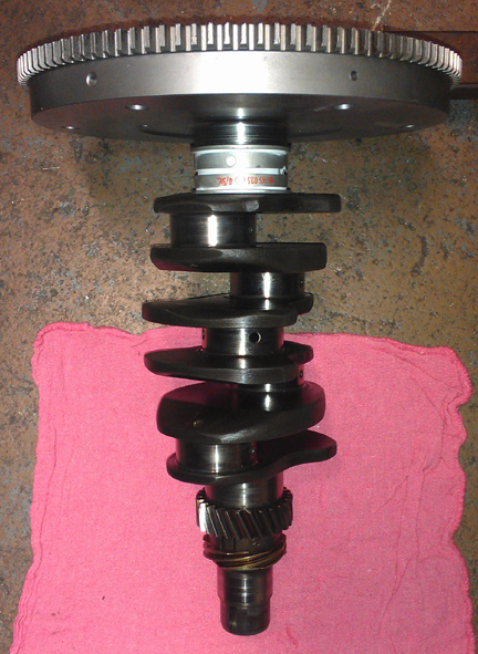
really like this engine, and it had an SC/912 crankshaft in it (counterweighted),
even though it's not stock, it's a bit better! And so, I decided to keep them
together. The crankshaft is "standard / standard" and it's in beautiful
condition. It was thoroughly measured, just to be sure.
I
really like this engine, and it had an SC/912 crankshaft in it (counterweighted),
even though it's not stock, it's a bit better! And so, I decided to keep them
together. The crankshaft is "standard / standard" and it's in beautiful
condition. It was thoroughly measured, just to be sure.
The original rods were fine, but I pretty much never put an engine out that has used rods in it, simply because if a rod ever does "let lose," the result is a completely destroyed engine.
 AT
RIGHT: A batch of rods - all late type, all done as described below.
AT
RIGHT: A batch of rods - all late type, all done as described below.
I rebuild rods in batches - it's easier / faster / cheaper that way as it keeps setup time to a minimum. All rods are balanced as a set and end-for-end to 0.1g, etc, as described below.
But could you believe it? ALL the rods pictured above have already gone into other engines! I didn't have any sets left on the shelf at the time I was ready to assemble the case halves. So, I started up on doing another batch of rods, but meanwhile, I don't want the engine stand tied up - that's my favorite stand! - so I went ahead and completed the crankcase without rods as they can be installed later. Later, of course, I got the rods finished and completed the assembly.
For me, "rebuilding the rods" means to:
This is all standard work so there aren't any photos of them in-process.
The order of assembly of the crankshaft isn't too vital. There's setting the end play with the flywheel and bearing, there's mounting of gears, and there's mounting of the rods. In this instance, I happened to leave the rods for last, and went ahead and set the end-play.
The flywheel is a stock one, freshly refaced, with a new pressure plate, and the pair balanced together. It's a 200mm version, 6v starter ring gear.
In setting the end-play, the best way is to install everything the way it would be in-situ, except not in the actual crankcase, and torque it up. You then measure with a feeler gauge the gap and swap out shims until you get it right. Then, a new iron gasket is used for final assembly later, after the case halves are assembled.
BELOW: The pressure plate and flywheel and the setting of crankshaft end-play, all as described above.
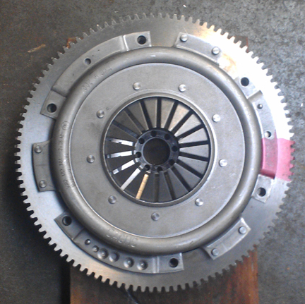
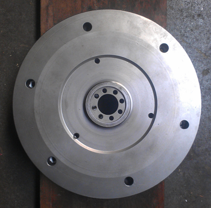
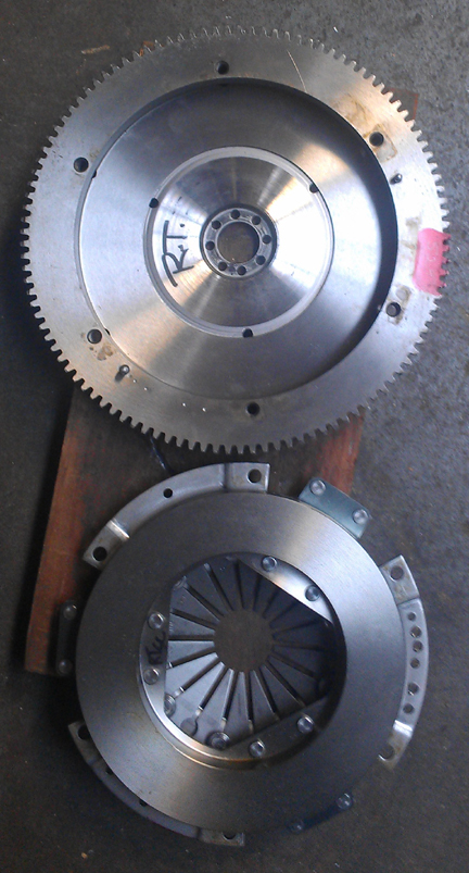
The buyer will need to provide their own friction disk.
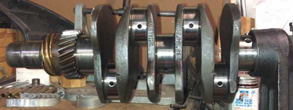
 The
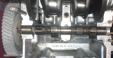
camshaft that was in this engine previously was a genuine Porsche, wide lobe
"SC" in great condidtion, so, following careful inspection, I decided
it should be re-used. You can see the Porsche logo between the rightmost pair
of lobes. (It's upside down.)
The
camshaft that was in this engine previously was a genuine Porsche, wide lobe
"SC" in great condidtion, so, following careful inspection, I decided
it should be re-used. You can see the Porsche logo between the rightmost pair
of lobes. (It's upside down.)
Meanwhile, the original lifters looked fine, but in an abundance of caution, I refaced them. If you're going to re-use them without refacing, they should go back in the exact spot they were in before, and when you change the cam, you must reface the lifters. It's always a safe choice to reface... The lifters are a late ATE version, marked 3900, and there are no known problems with them, unlike some of the earlier iron ones that sometimes lose their heads!
You can see the lifters as the case halves go together (below).
 Crankcase
Assembly
Crankcase
AssemblyOne of the first things one does is check the bearing fit, and on this standard crankcase, that went quickly. The new bearings are not the modern ones Stoddard sells today, which are a heavy type with little crush. No, these are old school Originals. The old ones are much lighter and the full-circle bearings are a little larger in diameter for the original amount of "crush" to hold them tight in the case - long since out of production.
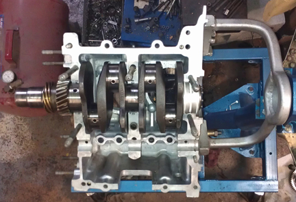
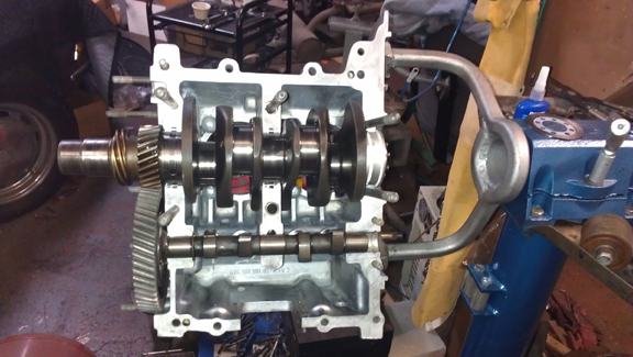
AT RIGHT: The left half is ready. Note the SC crankshaft, and on top of the engine stand, the already fitted end-play shim and new iron gasket for the end of the crankshaft. And doesn't this crankcase just gleem ... on the INSIDE!
Next, one sets the crank in place, pushes the thrust bearing home on it's dowel pin, and checks the fit of the camshaft.
In the image at right, notice the main bearings: The two "middle mains" (bearings 2 and 3) are each "halves". This is characteristic of C era crankshafts and their bearings as the middle mains are both 55mm in diameter (nominally), while on the earlier B cranks, the journals are 50mm. So these bearings are bronze or steel backed as they are about half the thickness of the B bearings they supercede. If bearing three is a full-circle bearing (you have to take the gears off to access it), then it's a B crankshaft! This is definetly a genuine C as confirmed in these images.
Also worth pointing out here - as described in the cam section above - that I refaced the cam followers. You can see the refaced lifters at right - the opposing pizza-slice shaped reflections give them away.
The cam was trial fit, and, I actually had to de-select the first one chosen (the original C from the core I received), but as described in the camshaft section above, it was flawed. So the image in that section shows the actual trial-fit to match up the cam gear.
 I
take special care with cam gears. One thing I always do that not many other
engine builders take the time for is polishing the teeth of the drive gear that's
mounted to the cam. I do this because firstly there's usually a bit more dirt
in between the teeth than most people realize, and taking time with every tooth
helps guarantee they're clean. Secondly, a coating of oxidation can make the
gear appear to be bigger than it really is, and when the oxidation wears off
(fairly quickly - contaminating the oil, by the way), the gear becomes a bit
looser. Unfortunately, I didn't realize my photos didn't show very much of the
polished gear until after the halves were together! Oh well, you can look at
other engines I've built and see what I mean - I nearly always do this unless
the gear was just in service.
I
take special care with cam gears. One thing I always do that not many other
engine builders take the time for is polishing the teeth of the drive gear that's
mounted to the cam. I do this because firstly there's usually a bit more dirt
in between the teeth than most people realize, and taking time with every tooth
helps guarantee they're clean. Secondly, a coating of oxidation can make the
gear appear to be bigger than it really is, and when the oxidation wears off
(fairly quickly - contaminating the oil, by the way), the gear becomes a bit
looser. Unfortunately, I didn't realize my photos didn't show very much of the
polished gear until after the halves were together! Oh well, you can look at
other engines I've built and see what I mean - I nearly always do this unless
the gear was just in service.
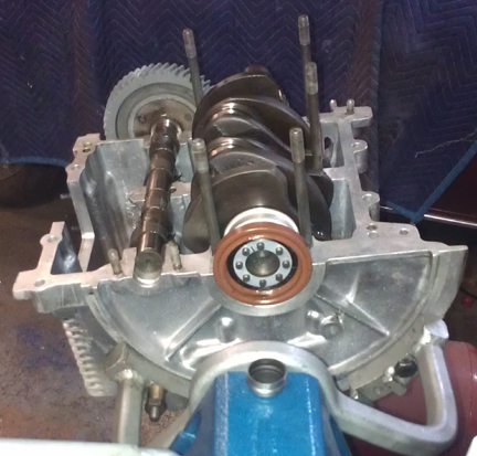
AT RIGHT: Here, from another angle, the left half, now with seal, shim and end-gasket in place. And note here how the OUTSIDE of this engine gleams too!
Now, time to put the case halves together! Prep-work done correctly, this goes easily and quickly. Apply sealant and bolt it up!
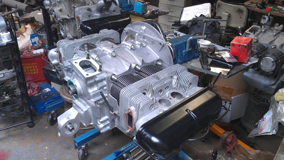
That goes rather quickly, the timing cover goes on, and here we have it as a "bottom end," also known as a "short block."
 Cylinder
Heads
Cylinder
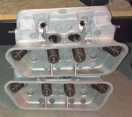
HeadsThese heads (at right) are Genuine C heads, and are in very good condition - no cracks ever, no broken fins, etc - and were mated as an original pair from new. And note how they gleam! Here's a summary of their features:
The heads are not the original pair from this engine. This engine was previously fitted with SC heads, but I put them on an actual SC engine! These heads are nearly as good - the only difference being the black anodization which increases the thermal emissivity (sheds heat a little better).
In the summer of '63, Porsche decided to save on production costs by making only one cylinder head casting for each of its two pushrod engine offerings, so, of course, they went with what the higher performance SC needed. However, to offer a lower-cost, lower-HP version, they merely bell-shaped the bottoms of the intake manifolds to the previous design (Zeniths), and the result was a bit of a mis-match; the air flowing through the manifold tends to lose some velocity right as the manifold joins the larger ports in the head. This is a well-known design oops that they apparently did on purpose because it just doesn't matter that much since the carburetion sitting on top of it was restricted anyway - and maybe they even wanted to lower the HP a bit more!
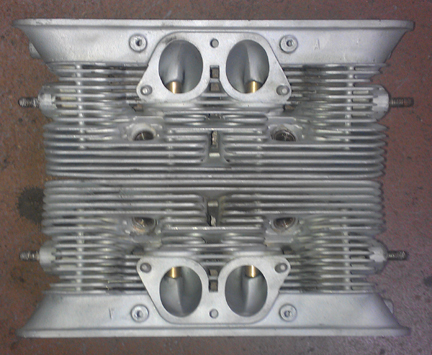
However, because the port design is the same as SC, and because this engine has the SC crankshaft AND SC camshaft AND the stiffer valve springs, I recommend completing this engine with Solex 40 PIIs, instead of the Zeniths.
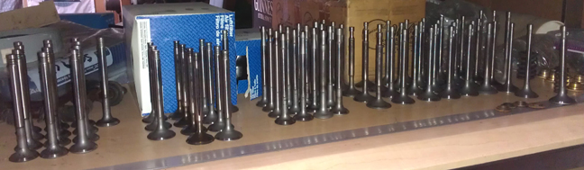
As noted above, fitted to these are great valves. They're originals, not aftermarket replacement which are all you can get new today. Of course, the valves have been checked for length (stretching makes them unworthy), polished, and refaced, so they're effectively perfect.
New springs, of course, carefully selected. Previously, we went through a large batch of about 40 new springs and they were grouped by strength. We match up slightly stiffer springs with the heavier valves (intakes are about 2% heavier than exhausts), so they're very close sets, matched up, so all the valves tend to float at the same time. ...Of course, each valve and retainer are position-specific through the shimming process...
The valves were selected from the cache of valves shown here, all re-faced and with stems polished (below right).
 After
the valves are fitted, the combustion chambers are measured with a burrette.
The results go into a process of matching up with the "CAC" data collected
earlier (and described below). This helps guide the decision on which head goes
on which side, what, if any, shimming will be used, and what additional remedial
action might be taken to improve the matching of the cylinders to each other;
the more similar the net HP produced among all cylinders helps improve overall
engine output, engine tractability, and longevity.
After
the valves are fitted, the combustion chambers are measured with a burrette.
The results go into a process of matching up with the "CAC" data collected
earlier (and described below). This helps guide the decision on which head goes
on which side, what, if any, shimming will be used, and what additional remedial
action might be taken to improve the matching of the cylinders to each other;
the more similar the net HP produced among all cylinders helps improve overall
engine output, engine tractability, and longevity.
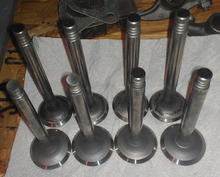 AT
RIGHT: Here are the valves actually selected.
AT
RIGHT: Here are the valves actually selected.
Given the old adage, "there's no replacement for displacement" - and there isn't! - this great set of Porsche Big-Bores is being fitted. These are 86mm, as is the usual for "big bore" equipped engines in the modern era. There's larger available - and custom can always be implemented - but 86 is a reasonable upper limit as an engine is a complete system and if you go larger than 86, you'll have other problems to address. ...As it was, a set of new 86mm pistons and cylinders obtained from the late Duane Spencer, with JE made forged pistons...
We always check the match of pistons to cylinders and match piston weights as a set, and provide any remedial action to correct any errors before installation. For example, by shuffling around the piston pins among the pistons, one can usually improve the matching of piston weights. This set naturally balanced to within about 0.2g (official specificaiton is 10g), and simply shifted which pin went with which piston to bring them into virtual perfection.
So, now the pistons and cylinders are ready.
For many shops, from this point, installation goes very quickly, but we think this is where one needs to take one's time! The key reason one needs to take time here is that there are production tolerances on every part in an engine, and while a set of parts may look identical, there's often subtle variation between members of a set, and there are sometimes significant errors in production that weren't caught by the manufacturer's quality control processes. These errors can "stack up" and cause problems if not discovered and corrected.
Here's our process: Two of these steps require special tools most shops don't have.
We like to carefully measure everything and then mix-and-match the parts for superior fit. We have also discovered significant manufacturing errors with this process which would likely have gone unnoticed without these measures. It is remarkably easy, for example, to overlook the circumstance of the crankshaft bore not in the true center of the crankcase, angled on the horizontal left or right of center, or not on the same horizontal plane at all. Yet examples of errors like these are not as uncommon as we would like.
<IMAGES NEEDED>
The next thing we do is something nobody else does (that we know of) in the engine building process, and that is to measure the height the piston crown comes above the plane of the top of the cylinder. I call this the CAC, or "Crown Above Cylinder." This value is important because, firstly, it can reveal deeper problems, and because it helps us get the compression ratio equal in all four cylinders.
Here are some of the deeper problems that can be discovered through a CAC check:
In order to do this for these engines, you have to have special tools. Here, you can see them in action on this engine in the images above.
Even if you can't read the needle in the CAC measurement image, the distance between the smallest tick marks is one hundredth of a mm, or 0.0004" - that's less than half a thousandth of an inch! - and you can discern to perhaps a tenth of that! So, this is a very accurate measure, performed while the cylinder is under torque, so any shims are squished flat, etc.
The accuracy is so good, that if you take the time to swap parts around, you can accurately determine discrepancies in the manufacture of the various parts! Yes, we ARE splitting hairs here! However, a benefit to both engine builder and customer is that the ability to move parts around for better fit means that perfection is more easily achieved, and the more equal the HP production of each cylinder, the smoother the engine will run, and the more HP the engine will produce overall.
Because this process includes the entire assembly, torqued as in service, and measures the height each piston protrudes out of its cylinder, all errors in connecting rod lengths, cylinder heights, crankcase spigots depths (cylinder bore deck), piston connecting pin heights, and shim thickness' are accounted for in the measurement results. There is no superior method.
After all of that, the rings were fitted per cylinder and end-gaps checked. Then the rings mounted, pistons mounted, and then the cylinders.
At this point the engine is ready for its cylinder heads, and this work went very quickly - as it should! - as all the prep work was already done.
Prepare the head "bolts" and washers, prepare the pushrod tubes, prepare the lower cylinder air deflection plates and their wire retainers, and get the torque wrenches set, and bolt on those heads!
My pattern is to mount one head, torque it to 7 ft lbs (as per the manual), then mount the other head the same way, and then alternate between the heads with an ever-increasing torque up to the final torque value, then repeat the final value until the fasteners no longer turn when torque is applied.
<IMAGES NEEDED>
OK, mount the valve gear, adjust the valves and pop on the valve covers - sounds simple and quick!
And, it should be, especially since the rocker's contact faces on the valve stems were previously refaced and showed little wear.
<IMAGES NEEDED>
Then fit the oil drain plug, and sump screen and plate. I used new cap-nuts to protect the studs into the future. (Recall, as noted above, that the oil sump studs were previously attended to - height-adjusted / replaced as needed.)
Then, fit the two oil control pistons. I used new springs because I figured the old ones had been compressed for some 50 years!
Can't forget the oil pump! In the images below, the cover for it is still in the parts washer - it should be gleaming just as much as the rest of the engine!
<IMAGES NEEDED>
NOTE: If this engine is sold as a long-block (which is planned)... One should NOT install the distributor drive gear without also installing a distributor because if anyone rotates the engine backwards, it will push the drive gear up where it can damage the bronze drive gear! Therefore, the distributor drive is NOT mounted until the last reasonable moment!
Because some people are keeping logs of VIN and engine numbers and then purport to tell people what someone else has, out of respect and concern for a buyer's privacy, exact VIN and engine number data are not published here.