Copyright © 2007 - 2025, Coachworks For contact data Click Here.
Copyright © 2007 - 2025
Copyright © 2007 - 2025,
Coachworks For contact data
Click Here.
![]()
MULTIPLE NOTICES:
This engine was a rebuild for a customer.
THIS PAGE IS UNDER CONSTRUCTION!
![]()
For convenience - to speed things up - this page started as a copy of a similar engine we did previously, found here. When we've got this engine's changes written up, this notice will be removed!
This page describes the complete overhaul of this engine.
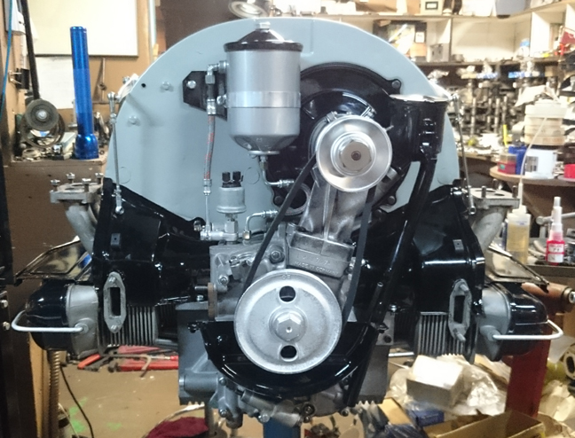
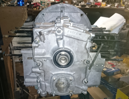
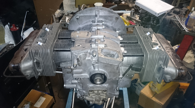
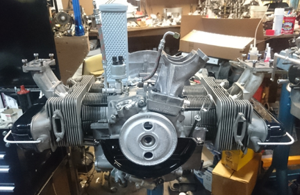
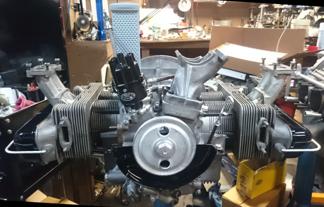
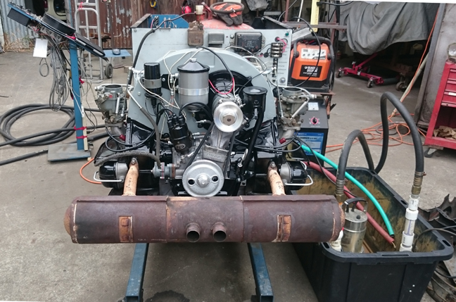
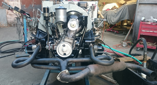
AT RIGHT: This engine, completed, run-in, waiting for its new owner. Nothing left to do but install it! Included items not pictured: fuel pump-inlet line, the muffler pipe and all remaining shrouding, powder-coated, including fuel pump shroud, firewall shroud, oil pump shroud, all thermostat pieces, and a reproduction rear pulley shroud ("breast plate").
Contents of this page:
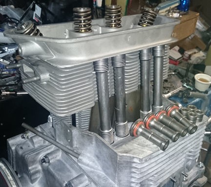
The crankcase is "numbers matching" and has been line-bored to second-oversize. It has the late-type oil pump, late rockers, late B heads, etc. It is fitted with mew modern biral (aluminum fins over iron) big-bore (86mm) cylinders with higher-compression ratio (9.5:1) pistons.
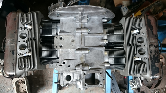
AT RIGHT: This engine nears completion. Remaining to be installed include the heating and exhaust system, the ignition system, the fuel pump, fuel line, and the carburetors.
Every detail about the engine has been attended to, as outlined below; nothing was left undone.
 Background
on This Engine
Background
on This EngineI received this engine from a customer in Florida. It had been run hard and put away wet, set aside decades ago when it began to lose power. Disassembly and inspection would show that it should have been set aside sooner because the bearings had been severly worn and the crankshaft had been pounding. Magnifluxing revealed that the crankshaft was nearly broken in two. And, as described below, the middle-main bearing saddles were pounded so hard, they didn't clean up when align-bored to first oversize.
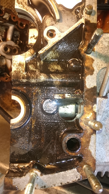
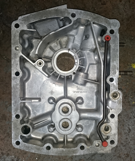
AT RIGHT: This case, in the parts washer. Note that cleaning had already started when it was realized that this one was unusually dirty and a photo should be taken! Note the brush strokes in the dirt - this image was taken after cleaning was already well under way!
Further, the internals were filthy and there had been water let stand in the engine. The crankshaft was rusty, as were the oil pump gears and there was water damage in one head.
Let this one serve as a reminder to change your oil regularly! This one had been completely ignored for a LONG time!
As noted above, the engine had been run pretty hard. It was obvious to the naked eye it was going to need an align-bore, which is a Porsche-approved method of renewing a crankcase; material is cut away to provide a new bearing surface, and a replacement bearing of special size makes up for the removed metal.
 After
cleaning, the case was then assembled with full torque and then align-bored
to "first oversize." Porsche provided for three official over-sizes,
for four total sizes: standard, 1st over, 2nd over, and 3rd oversize, moving
from 60.25mm nominal bore up in 0.25mm increments.
After
cleaning, the case was then assembled with full torque and then align-bored
to "first oversize." Porsche provided for three official over-sizes,
for four total sizes: standard, 1st over, 2nd over, and 3rd oversize, moving
from 60.25mm nominal bore up in 0.25mm increments.
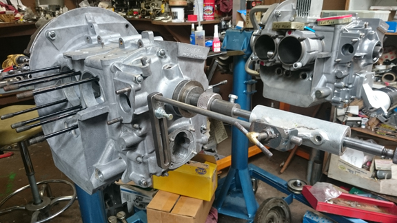
AT RIGHT: This engine (foreground left) is here ready for the align-bore process. The cut is effected by cutters mounted on collets which in turn are mounted to a shaft running through the crankcase supported by two iron fittings mounted to the case. The cutters are rotated via an attachment on the flywheel end, and a slow progression of the cutters axially is effected through the gadget seen foreground right.
Once the align-bore was completed, the results were examined.
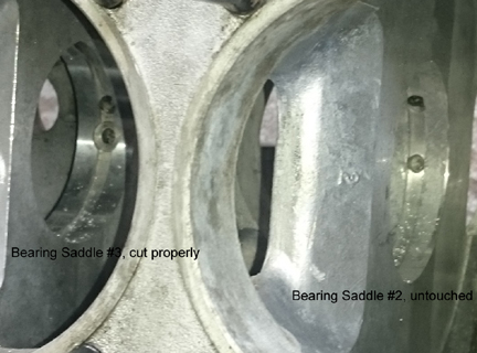
Unfortunately, the results were not great. The saddle for bearing 3 (third from the flywheel) cut cleanly and completely. The saddle for bearing 1 didn't quite clean up completely but I would have lived with it if that were the only issue. However, astonishingly, the saddle for the middle main bearing (bearing 2) had been beaten so hard the cutter didn't even touch the case! WOW!
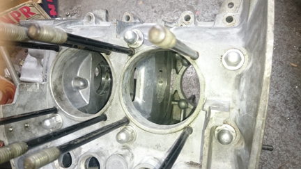
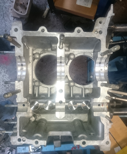
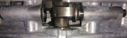
BELOW, LEFT & RIGHT: Here we can see how the middle main bearing saddle wasn't even touched while bearing 3 got a clean cut. Getting this photo without splitting the case (because another boring attempt was about to be made - at a larger size), was a bit tricky, so we've got a close-up for you on the right. (These two are the same photograph; the right one is a cropping and enlargement with text added to lable the bearing bores.)
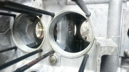
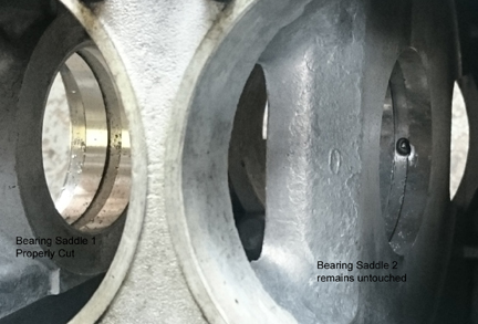
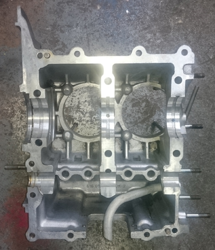
BELOW, LEFT & RIGHT: Here we have the same situation from the other side of the case, and this time showing the saddle for bearing 1 (on the left), and 2 (center / right). Again, the right image is a close-up of the same image found at left. Note that the cutter didn't touch the case at all for bearing 2! ... These images show the centering of the boring bar was pretty darned good, nearly perfectly concentric with the original bore.
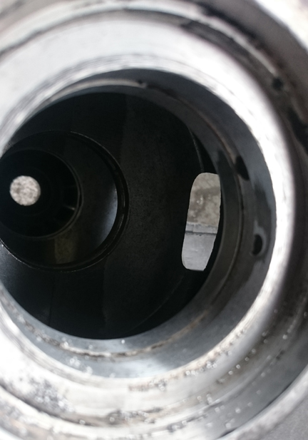 Just
for completeness, here's the bit on bearing 1 that didn't quite clean up at
first oversize. Note that we know the concentricity of the boring bar to the
original bore was practically perfect because the cutter didn't touch either
side for bearing 2, so this bit that didn't get cut on bearing 1 we know is
a low-spot...
Just
for completeness, here's the bit on bearing 1 that didn't quite clean up at
first oversize. Note that we know the concentricity of the boring bar to the
original bore was practically perfect because the cutter didn't touch either
side for bearing 2, so this bit that didn't get cut on bearing 1 we know is
a low-spot...
AT RIGHT: This shows the whole bore from the flywheel end, with the pulley-end support for the boring bar left in pace to help improve the odds that a second cut will bore concentrically. As noted above, the bearing saddle for bearing one (foreground) didn't cut completely and here we can see that as the dark areas on the right.
So, of course, the case had to be align-bored further. It was cut to second oversize, nominally 60.75 mm and it cleaned up nicely. I always bore to the small size of the tolerance range if I can.
Unfortunately, it was very hard to find main bearings in second oversize these days! Even though Porsche specified them all the way to third oversize, nearly nothing is available but standard and first over.
By luck, I found a set. It's a brand new (2016) reproduction I've never seen on the market before.
They LOOK OK, and I trial fit all of them into the case half without the crank. They seemed a bit tight but perhaps they'd be OK. However, it turns out they're a bit "fat". That is, they have a larger outside diameter than one would expect of originals. Perhaps this is good for someone who has a worn case already at 2nd over! However, in this instance, when trial assembly began, it wedged tight on the crank.
The first thing I tried to do was measure their OD but was shocked to find they were not consistently round! This is worrysome. However, the case will bring them back to round, so this is not necessarily a show-stopper, just disappointing - and causes extra trouble because you can't just measure them and know for sure what kind of error there is in the mismatch of case bore to bearing size. And that makes things a bit more of a guess based on experience.
Various efforts at removal of one of the bearings, etc, revealed that all of them were tight, and yet crankshaft clearance was very small. Measuring the bearing wall thickness showed them to be a tiny bit thicker than they should be, and I think this is where the key problem lay - the snugness in the case could be tolerated but it closed up the ID too much.
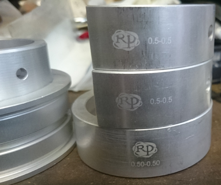
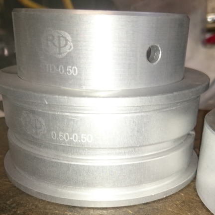
ABOVE, LEFT AND RIGHT: The brand-spanking-new brand of replacement main bearings for our beloved Porsche 356es! This was the first time I've ever even heard of them. I asked around - April, 2016 - and nobody else has ever heard of them, either! This set is 0.50mm larger than standard on the outside and 0.50mm larger than standard on the inside - also known as "20/20", and note that as is normal for Porsche 356 bearing sets, the nose bearing (#4) is standard on the case!
So, I had a decision to make... I'm reasonably good at doing some pretty amazing things with a boring bar, and all the other alternatives are EXPENSIVE, so, I set the cutters a TINY bit bigger and bored it again! I was shooting for a 1.5 to 2 thousandths increase in bore. It's vital that the concentricity with the existing bore be maintained! So, this took some three or four setups before I was happy with the cutter. And here's a secret: Align all the cutters in a row at the same new height. Then attempt to just push the bar through the bore without turning - the intent is NOT to cut! If it fouls the bore, good, it will cut there, now, try every few degrees - say every 5 - until you've been all the way around. If it ever just pushes through without touching, your alignment is off and you must take out the supports and re-install them! Repeat until you luck out and get a good, concentric alignment. See, this is simple! However, most people won't even try such a thing, considering a repeat bore impossible (as normally it is)!
Once cut, I measured the bore and while the new cut was not perfectly concentric with the first one, it wasn't visibly in error (see images above for visible error and images below for what it looked like after the second boring). And, very importantly, I was able to install the bearings without a crank in the second-cut-to-second-over bore and confirm they had good crush, and also found that the crush was not any longer so much that it interfered with the crankshaft, so the crankshaft turned freely as it should! -whew!- Need to further over-bore was averted!
BELOW, LEFT & RIGHT: The case, ready for assembly! Actually, I was so eager, I already put the freshly refaced lifters in the left half!
 Crankshaft
and Connecting Rods
Crankshaft
and Connecting RodsAs noted above, Magnifluxing revealed that the crankshaft was severly cracked, nearly clean through. One cause of this was that the middle main bearings were severly worn which allowed the crankshaft to flex on every cycle. In any event, a replacement crankshaft was obtained. It's second under-size on both rods and mains, but Magnifluxed OK and was freshly reground.
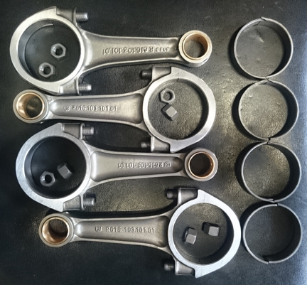
The owner chose to upgrade the rods to the C/SC/912 style.
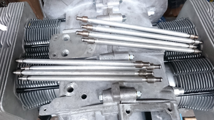
AT RIGHT: The set of rods that went into this engine.
For us, "rebuilding the rods" means to:
This is all standard work so there aren't any photos of them in-process. However, here they are, ready.
Unfortunately, I somehow overlooked getting an image of these rods dangling on the crank, or even of the bare crank - I guess I was too distracted by the main bearing issue?! - but I did get this image of the numbers on the crank that show the journals are very nice... I normally don't publish these numbers, but, oh well!
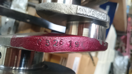
AT RIGHT: The only image I took of the crank before installing it. Oops! At least you can see the journals are freshly ground and polished.
I guess I was so concerned about the main bearings and I wasn't certain that was resolved until the case halves were together, and then, well, it was a little too late to take some of the photos I usually do at that point, such as the cam laying in the case half after selecting a timing gear, etc. Instead, the next thing you knew, we had a short-block!
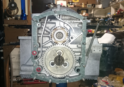
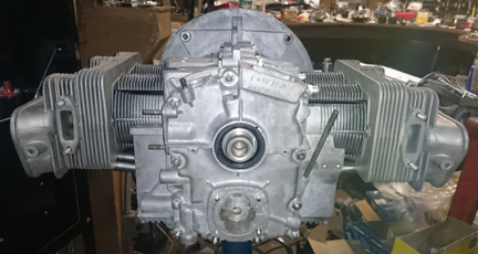
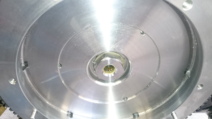
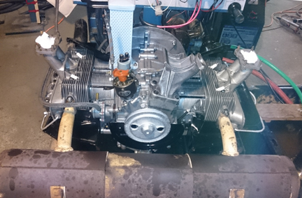
AT RIGHT: The engine as a short block. Beautiful! Note the seals are all in place, etc. While this is not a close-up, perhaps you can tell how NOT worn the oil pump drive slot is in the end of the cam - it's virtually perfect.
The engine is a super, but the camshaft that was in the engine was not! It was a well worn "normal." So, I selected a genuine original Super camshaft from my stash that is still in good serviceable condition and cleaned it and installed it here. I left the gear that it was mounted to mounted, and with just good luck, it happened to be perfect for this engine!
Next the timing cover was installed, the oil slinger, pulley oil seal, etc.
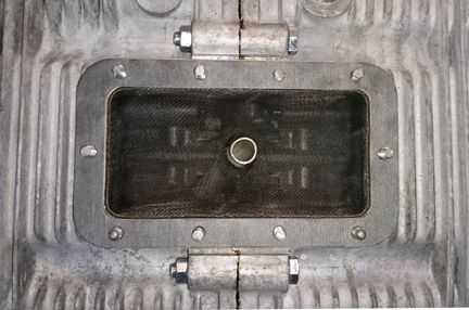
AT RIGHT: After realizing I was missing various images I usually take, I took this one through the oil sump plate hole in the bottom, so you can see the cam lobe. I rotated it so you're looking at the leading edge and tip of the lobe and you can see how it's in fine condition.
The customer selected to upgrade to modern biral, big-bore pistons and cylinders (86mm nominal bore) with nominally 9.5:1 compression ratio.
BELOW, LEFT & RIGHT: These are our new pistons and cylinders. The cylinders are "biral", which means they have aluminum fins cast over a standard iron liner. The pistons, meanwhile, are cast and are aproximately a high-compression copy of the venerable "NPR", which was the first big-bore available for the Porsche 356.
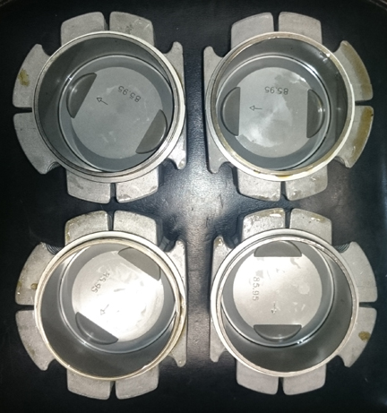
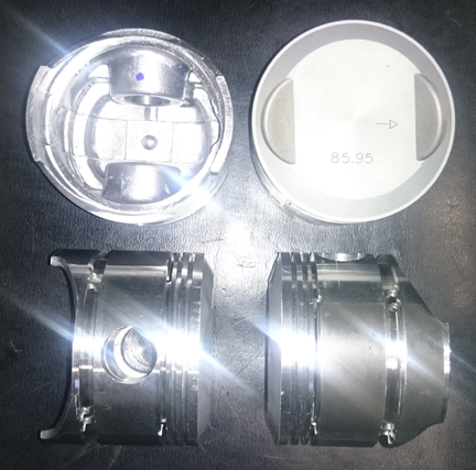
This set was cleaned of oil and the parts weighed. The connecting pins were moved around to make a better balanced set. Three are within 0.1 gram, and one was 0.5 gram lighter. Given that the specification from Porsche for weights within one set is 10 grams, a half gram isn't bad and seemed a shame to have to grind on three of them. So, even though we usually get them all to 0.1gr, we left them alone at 0.5 for the set.
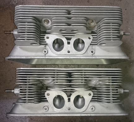
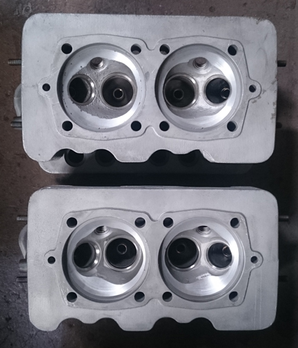
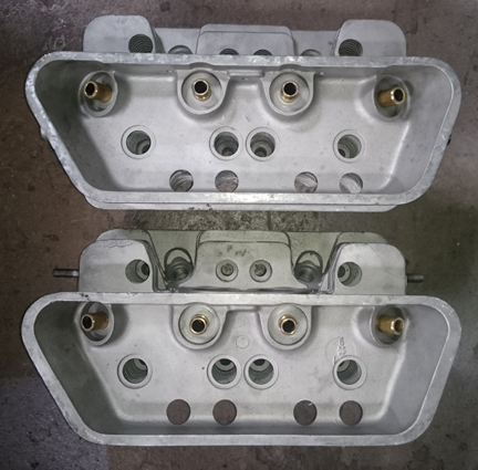
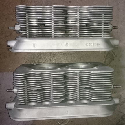
The heads that came with the core look matched in most all respects, but they have different casting hallmarks - doesn't mean anything, but I just happened to notice that one had a casting date (36/60) and the other didn't.
As is standard on ALL engines we build - no exceptions! - they all get new guides! On older engines with brass seats, those always get changed out to modern, unleaded-safe seats.... Of course, everything gets cleaned up. And, of course, when late type pistons and cylinders are mated to an earlier head, the heads are conically cut so there's no risk of the piston striking the head as would otherwise occur.
Here are these heads, ready for valves.
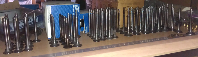
Generally, if a customer provides a core, I keep their valves with the project, and for my own work - engines done on speculation or for myself - I do batches of valves (they're cleaned, refaced and stems polished) from which I select the set of valves to be installed. In this case, however, the "core" valves were mostly not serviceable. In several cases, the valves had been refaced too many times and would be too thin, and the remainder had too much stem ware - no doubt due to the terrible oil that was circulating in the engine. So, I grabbed a set from here:
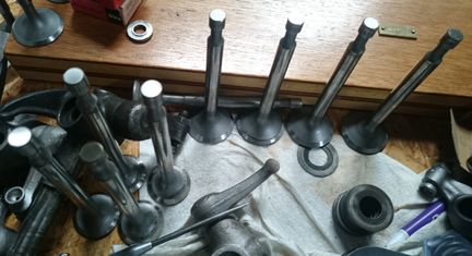
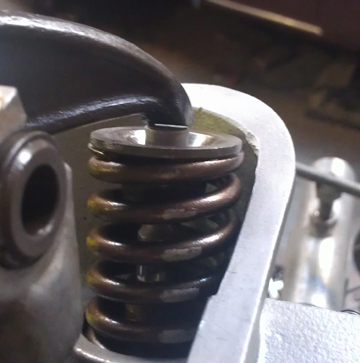
AT RIGHT: Here are the ones selected, next to the spring compressor, about to be installed. The valves have been re-faced on their seats and stem ends and the stems were polished.
As noted above, the seats are ground, new springs installed, and carefully reassembled with shimming to match all the valve spring tensions. This way the valves all reach their RPM limit at one time and the driver knows it because of loss of power. We think it's horrible to have one or a couple of valves floating while the others are OK because the driver doesn't have any way to know it and may continue on, damaging the engine; when they all float at once, the driver knows...
I always check all threaded bores and studs. The retainers and keepers are standard "B" type, correct for this engine, but the customer wants - and provided - the late aluminum rocker stand. Porsche itself did this in 1957 for the first S90 engines (well, actually the first ones were magnesium, and were prone to breaking), but sometimes there's a fitment problem with a valve retainer. We're trusting to luck here!
Following all this, I measure each combustion chamber's volume. Given very accurate measure of both the volume in the head and the contribution from each cylinder, one finds that there are always varriations in both, and it is not always necessary to match head volumes because it may be possible to move the head from one side to the other and improve the matching very much. These considerations are covered in more detail in the section below where the pistons and cylinders are installed.
 Assembly
to the long-block stage
Assembly
to the long-block stageFor many shops, from this point, installation goes very quickly, but we think this is where one needs to take one's time! The key reason one needs to take time here is that there are production tolerances on every part in an engine, and while a set of parts may look identical, there's often subtle varriation between members of a set, and there are sometimes significant errors in production that weren't caught by the manufacturer's quality control processes. These errors can "stack up" and cause problems if not discovered and corrected.
Here's our process: Two of these steps require special tools most shops don't have.
We like to carefully measure everything and then mix-and-match the parts for superior fit. We have also discovered significant manufacturing errors with this process which would likely have gone unnoticed without these measures. It is remarkably easy, for example, to overlook the circumstance of the crankshaft bore not in the true center of the crankcase, angled on the horizontal left or right of center, or not on the same horizontal plane at all. Yet examples of errors like these are not as uncommon as we would like.
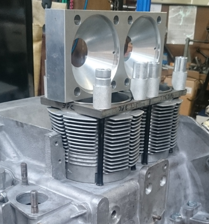
ABOVE RIGHT: Here's an image of checking the cylinder heights for matching their neighbor. The book tolerance is 0.1mm (four thousandths of an inch, 0.004). Because this process measures with cylinders and their shimming installed, torqued, it results in a very acurate and reliable comparison of cylinder heights. In this case the inner edges of cylinders 3 and 1 were both about 0.0015" low, and perfect in all other respects, so they're OK.
AT RIGHT: And here's an image of checking how far each piston protrudes from its cylinder. (For the sharp-eyed, yes, this is a different engine being checked - the images above and below just shows the tools and the process used.)
Because this process includes the entire assembly, torqued, and measures the height each piston protrudes out of its cylinder, all errors in connecting rod lengths, cylinder heights, crankcase spigots depths (cylinder bore deck), piston connecting pin heights, and shim thicknesses are accounted for in the measurement results. There is no superior method.
During this process, the pistons and cylinders are often moved around some, sometimes with different shimming combinations, all in an effort to get the compression ratio equal among all cylinders, and the last step is to install the piston rings and pin circlips.
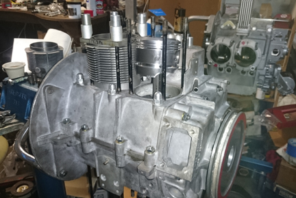
AT RIGHT: Here, the pistons and cylinders are being moved around to try and get a better match for compression ratio from the various cylinders.
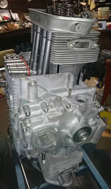
Now, with the pistons and cylinders sorted, it's time to mount the heads, pushrod tubes and lower cylinder air deflectors and torque them on. For this, per side, I staged the parts as you can see below.
Harry Pellow had it right, we believe, "sneaking up" on the torque, shifting from the right head to the left and back until at final torque, etc.
At this point, since all the prep-work is long since done, it's a fairly quick process and before you know it, you have a long-block - not too much time for thinking about taking photographs! These images show the results of about a half-hour worth of "put 'em on, and bolt 'em up."
OK, some final bits here - oil control pistons, oil pump, sump screen / plate, rockers, valve adjustment... It goes pretty quickly if you've prepared things properly... It turns out that the core's sump screen was the wrong one - for a younger engine - so I just swapped it out for this very nice one.
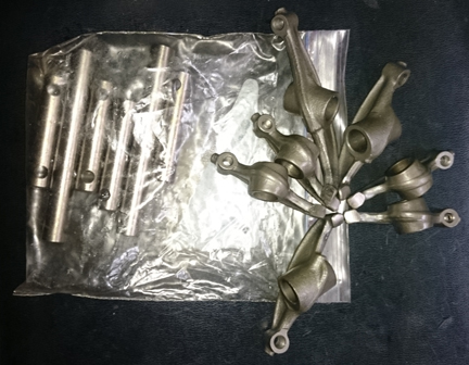
The rockers received a bit more preparation than just cleaning. Of course they were thoroughly cleaned, but they were also "hard-faced". This is a process by which new, much harder metal is welded on to the contact faces where the rocker pushes on the valve stem. In service, this surface wears with time and eventually it wears through the original hardening applied by Porsche. When this happens, it's very hard to maintain proper valve adjustment, both because it wears so much faster than usual and also because a "step" is often worn into the rocker making it difficult to get a feeler-gauge inserted, therefore distorting a perception of what the lash actually is. After this harder material is welded on, it is then re-faced on a special jig that ensures the contact surface has the correct orientation to the valve stem - this cannot be done by hand, though some shops do try to do that! (Here's a photo of the results of someone having done just that. Note in that image how the rocker only contacts the valve at the left-most edge. This is because you simply cannot free-hand refacing a rocker.)
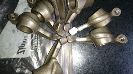
BELOW, LEFT & RIGHT: The rockers, cleaned and hard-faced. In the close-up on the right, one of the rockers is rotated slightly, so you can see the thick, hard-face material as a distinct layer over the original rocker material. The rocker shafts have been polished, of course! And, one rocker seems to have been set on the work bench for when these photos were taken! Oops, to late to re-stage the photo now!
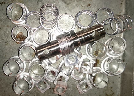 The
rockers were installed with this hardware:
The
rockers were installed with this hardware:
AT RIGHT: These bits are the springs, and the shims and seats that they push against that keep the rockers gently drifted to one side as the oscelate.
And, finally, we have a long-block... Note that the valve covers will be refinished in the next stage as the engine gets built-out to turn-key status.
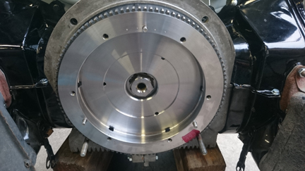
...Somewhere in this timeframe, the flywheel got mounted. It's a 200mm modern reproduction, new of course. It's attached with a new, genuine OE gland nut - very expensive! However, I didn't think to take photos of this until later. Here it is mounted:
I was also a little late to realize I'd forgotten to get images of the valve gear installed. So, here you go! It doesn't really show well here, but all the hardware is plated, too including the side-load springs, shims and "hats" that go around the shafts.
Once the long-block was done, attention turns to the "accessories" (fuel pump, distributor, etc) and making things both look great and be great.
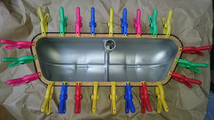
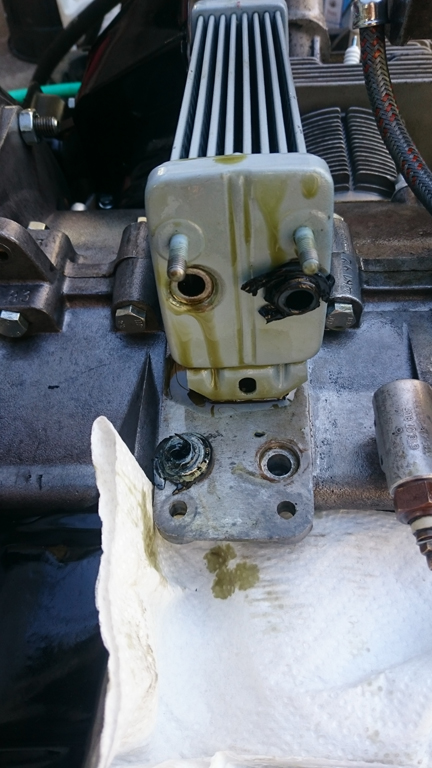
While the process of creating a long-block was underway, the fuel pump and distributor were rebuilt, and the oil cooler was flushed, tested, then repainted.
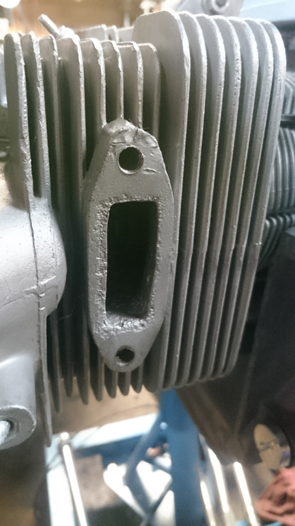
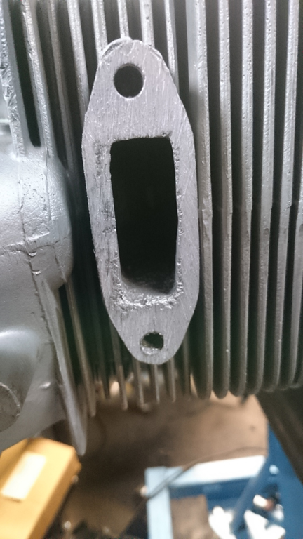
One thing that could have been dealt with earlier but became apparent something should be done at this point was the observation of some port damage on the exhaust for cylinder four. Here, we see the damage and the repair. The solution was to remove the studs and file the surface flat.
 Installing
things onto a long block goes very quickly if you've done your preparations!
So, the oil system goes on straight away - keep any dirt from having a chance
to get in there! The oil cooler is first, then the oil junction block standpipe,
then the temperature sending unit block, with sealing washers, the sender itself,
then the oil pressure sender.
Installing
things onto a long block goes very quickly if you've done your preparations!
So, the oil system goes on straight away - keep any dirt from having a chance
to get in there! The oil cooler is first, then the oil junction block standpipe,
then the temperature sending unit block, with sealing washers, the sender itself,
then the oil pressure sender.
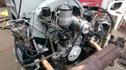
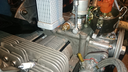
AT RIGHT: Rear view as the engine assembly proceeds. The valve covers and pulley shroud are powder-coated, and most all the hardware (including the valve cover bails, crankshaft pulley, dip-stick and a lot of smaller pieces) have been plated, though the real emphasis isn't on "bling", but just a quality assembly.
Note that in this instance, the oil pressure sender will be used on the dynamometer and is a dual unit - both "idiot light" and feeds an actual analog gauge. It will be removed following the dynamometer run.
The intake manifolds and generator stand aren't far behind!
BELOW, RIGHT & LEFT: At left we see a close-up of the upper rear portion of the engine - even the oil pressure control piston's retainer has been re-plated so it won't rust. Note the hardware detail. At right, we see a seldom photographed aspect of engine assembly; the valve cover gasket should be seated on the cover with the builder's favorite sealant. This permits it to be removed and replaced when desired - because it's on the cover and therefore easily moved to a workbench for cleanup - and it keeps the gasket in place so it seals. Without this step, leaks often develop as the seal fails to remain in position at the perimiter of the cover.
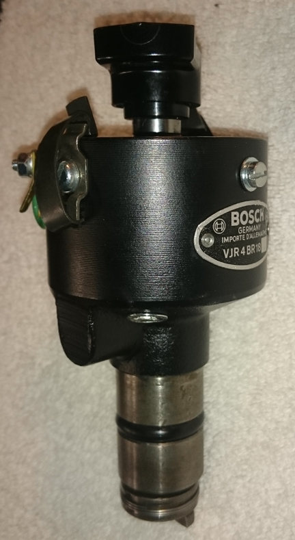
Along the way, the distributor was rebuilt:
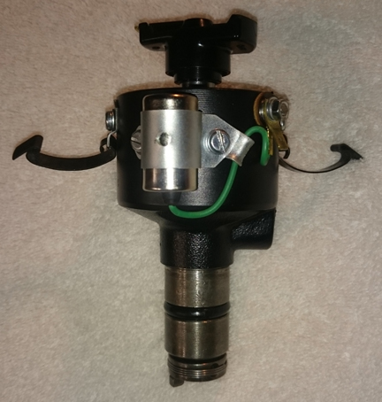
Then, the distributor drive gear is inserted and the distributor is mounted, resulting in this:
There's more to this than meets the eye: The rotational position of the drive gear matters greatly. In theory, any position can work but as a practical matter, the base of the distributor casting has a lug that will interfere with the edge of the third piece of the crankcase and also the oil pressure sending unit gets in the way of the condenser. And, there must be room for adjustment of the ignition timing. Therefore, the rotational position of the drive gear matters a lot.
In any event, the distributor has to come out again for various steps because, for example, it's far easier to complete the oil line connections with it removed. However, one has to be careful not to rotate the engine whenever the distributor is out because the drive gear can walk up and jam in the brass crankshaft gear, leaving behind metal particles in the oil.
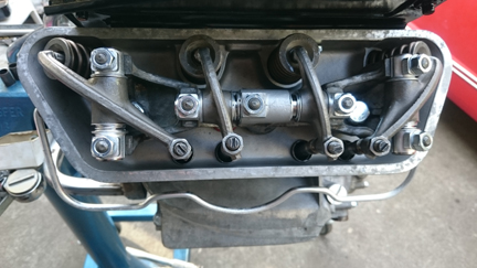
 A
demonstrably not well attended to area of concern is the breather tube where
it exits down through the closing sheetmetal. Owners and / or engine builders
famously ignore this completely - or, perhaps, they don't know what to do about
it? Hmmm... In any event, the issue is that any mis-alignment of the breather
tube through the sheet metal results in the tube being cut by years worth of
vibration. Notice this engine's breather tube has already been cut through and
a new bit of smaller diameter pipe has been added as a repair. And note that
the spot where it was cut is precisely the spot where it transits out of the
engine bay to the area below.
A
demonstrably not well attended to area of concern is the breather tube where
it exits down through the closing sheetmetal. Owners and / or engine builders
famously ignore this completely - or, perhaps, they don't know what to do about
it? Hmmm... In any event, the issue is that any mis-alignment of the breather
tube through the sheet metal results in the tube being cut by years worth of
vibration. Notice this engine's breather tube has already been cut through and
a new bit of smaller diameter pipe has been added as a repair. And note that
the spot where it was cut is precisely the spot where it transits out of the
engine bay to the area below.
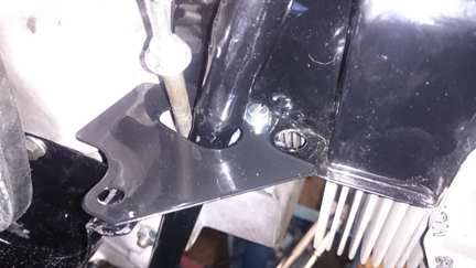
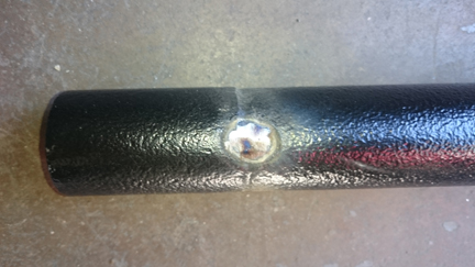
AT RIGHT: The breather tube exiting through the sheet metal as described in nearby text. Note the tube diameter change! Also note that this is the "after" image where it is properly centered in the hole provided. It should not touch the surrounding metal at all!
The solution, of course, is to bend the tube into a centered position! However, when the upper cylinder shroud and the small metal foot that provides a spot for the shrouding to be bolted in (here plated "silver", retained by black screws) are mounted, bending the tube to the right spot is inhibited because, due to the nature of metals, you have to bend it past the point you want it and it will "spring back" a bit. Therefore, these pieces must be removed and reinstalled a few times while you iteratively bend the tube and trial fit a few times, confirming it's right, or taking the pieces out and bending again! Do what it takes! (Note that, alternatively, a busy workshop like we have provides an alternative ready solution: Mount an appropriate era generator stand on another crankcase and mount the breather there for bending purposes. This means that only the breather needs to be re-mounted a few times and not the sheet metal and small metal bracket. This saves a lot of time.)
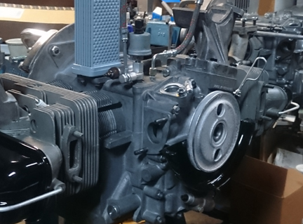
AT RIGHT: The engine is getting close here. Note that the oil pressure sending unit is on loan for the purpose of the running-in process on the dynamometer. The distributor was dismounted for this photo to show the oil junction area behind. Missing items include the ignition system, exhaust and heating system, and the fuel system!
Around this time the engine stand was wheeled outside and the big floor jack - "Big Birtha" - was used to lower the engine and install it onto the dyno. First, however, some last minute tasks were attended to. Here, we see the left carb being fitted, but also, note the large open hole. A plug for this hole was made and installed right after this image was taken:
AT RIGHT: Here, the large hole in the top of the carburetor can easily be seen. Normally, one replaces the top with one that hasn't lost this "soft plug". However, none were to be found at a reasonable price, so a plug was made and installed instead. It's visible below, but not this close-up. Also note the reproduction spark plug wire end. These were briefly back in stock a few years ago but withdrawn from the market because they often go faulty as, indeed, this set did during running tests on the dyno prior to the run-in phase.
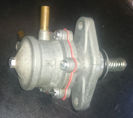
BELOW LEFT: Here, the fuel pump is done. The top provided had a bad bleed-back valve which prevents fuel from returning to the tank. That valve is not included in rebuild kids from Porsche and the best solution is to simply replace the top with the valve, and that was done here. All the parts were soda-blasted clean. The springs and diaphram are from the new kit and the top, top bolt ,and screws are all re-plated originals.
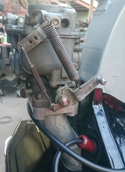
AT RIGHT: The engine, mounted to the dyno. Some things to note here: the left-hand carburetor has a red dot visible near the top. That's a fiber plug that I made to replace the "soft plug" that fell out. The hole was necessary during manufacture for performing a machining operation and it's closed off with a part that apparently fell out. No replacement tops were available, so I made the plug. Also, the sharp-eyed can notice a brownish-red color at the end of the spark plug wires; these are the spark plug wire ends - reproductions that were available a few years ago and taken off the market due to running faults. Also, of course, the fuel pump, coil, and remaining parts were fitted.
AT RIGHT: A close-up of the left side. The fuel line is more visible here.
The first phase of running is before a load is put on the engine, when throttle adjustments and various checks are made, ignition timing set and so forth. The distributor was found to not have enough spring tension and so it refused to return to the idle position. It was then swapped with an 022 so the run-in process could proceed with out delay.
BELOW, LEFT & RIGHT: At about 45 minutes into the run-in process, at a little over 3000 RPM, both oil cooler seals burst! It made a huge mess! Post disaster investigation concluded that it was a time & temperature based failure as both burst within seconds of one another - faster than I could realize what had happened and shut it down! The seals were replaced with aftermarket ones made of better type of material favored by people who run their engines very hot. Note that the vast majority of the oil was already cleaned up by the time these photos were taken! It was positively everywhere!
ABOVE RIGHT & BELOW: Note that the tear-down required to clean up the oil was considerable! All the upper sheet metal had to come off. Later, the loaner exhaust and flappers were removed and replaced with clean ones! The new cooler seals are a reddish pink! Also note that during the dyno running phase before a load is placed on the engine, the distributor was checked for proper advance curve and shown to have weak return springs. So, while they were being replaced, this 022 was used for the run-in instead. It was swapped back to the BR18 just before the final running seen below.
 Following
the run-in, the last of the powdercoating was available so, the exhaust and
flappers were swapped out and a final running of the engine conducted. As the
J-Pipes were media blasted as a part of the powdercoating process, it exposed
a hole in one pipe which was welded closed and ground smooth.
Following
the run-in, the last of the powdercoating was available so, the exhaust and
flappers were swapped out and a final running of the engine conducted. As the
J-Pipes were media blasted as a part of the powdercoating process, it exposed
a hole in one pipe which was welded closed and ground smooth.
AT RIGHT: The left j-tube (and exhaust pipe) had a hole welded up.
BELOW LEFT & RIGHT: The engine was finally finished off completely and then run again to check for exhaust leaks and a second check of the distributor following the new spring installation. The result was a nice happy idle at about 650 RPM. Note the great oil pressure - and this was after warm up, so the engine oil is fairly thin at this point.
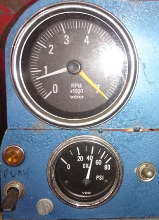
I actually tweaked it down a little, and got it to as low as 550 - nice and steady, very stable - but it would stall when run higher and suddenly dropped to an idle.
Because some people are keeping logs of VIN and engine numbers and then purport to tell people what someone else has, out of respect and concern for a buyer's privacy, exact VIN and engine number data are not published here.