Copyright © 2007 - 2025, Coachworks For contact data Click Here.
Copyright © 2007 - 2025
Copyright © 2007 - 2025,
Coachworks For contact data
Click Here.
![]()
 Porsche
Engine
Porsche
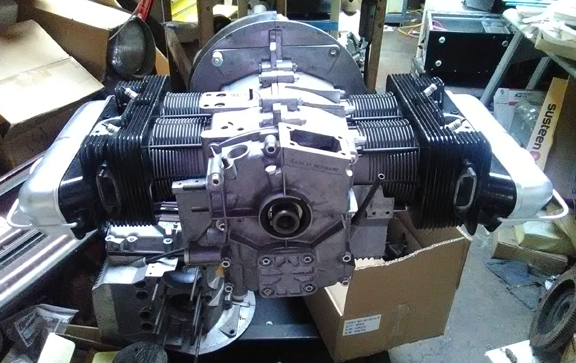
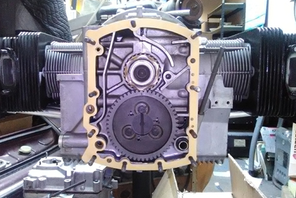
EngineAT RIGHT: Ready! Just add your completion parts - or ask us to provide them for you!
This engine has been prepared in long-block form, but may be purchased complete, ready to install, with only a few days delay.
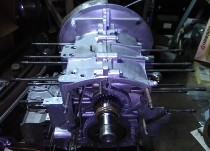
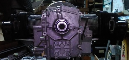
BELOW RIGHT: This engine from the rear, ready for its "accessories." Yes, that number area where the engine serial number goes is blank, but the two halves are matched 616/16. Sharp eyed viewers will note in the image above that yes, that's a 911 engine building stand and yes, in this and the above image, that's a 911 at left of this stand.
 This
engine is optionally available Run-In on our Stuska water-brake
engine dynamometer as per Porsche factory specifications as outlined in
the Workshop Manual, operations 52 EN, 53 EN, and 54 EN, pages E83 and E84.
You can see this being performed on another of our engines here
- see the second image down. We can provide "loaner" parts for this
process on request.
This
engine is optionally available Run-In on our Stuska water-brake
engine dynamometer as per Porsche factory specifications as outlined in
the Workshop Manual, operations 52 EN, 53 EN, and 54 EN, pages E83 and E84.
You can see this being performed on another of our engines here
- see the second image down. We can provide "loaner" parts for this
process on request.
This 356 SC engine has just undergone a complete overhaul, and is fully balanced for smooth running, long life, and a few more HP.
This engine started life as a type 616/16, better known as a 356 SC engine, and at some point a new replacement timing cover was installed. We do not know why the timing cover was replaced, however, no numbers were ever stamped into the cover. We have restored this engine with all the top-quality steps we are well known for such as all new valve guides, new valve springs, etc, and we have included a new cam and new "biral" (aluminum fins over an iron liner) cylinders with 9.5:1 (nominal) compression pistons, just as the originals were, except that they're "big bore" at 86mm (for a total displacement of 1719.4cc).
During this rebuild every detail has been attended to; nothing was ignored or overlooked.
This engine came to us from a customer who bought a similar engine from us and, he wanted to sell us his core for credit against the engine he was buying, so we tore it down immediately. We don't know anything more about it than that except what we could infer from what we found inside - which we largely describe in this text.
 Crankcase
Preparation
Crankcase
Preparation This crankcase cleaned up nicely and didn't need any special preparation before reassembly. The case was previously align-bored to second oversize and is maybe even a bit on the tight side - which is good!
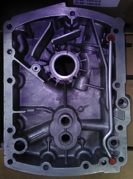
AT RIGHT: The right case half, ready for assembly.
Unfortunately, the images of the left half, bare, didn't turn out very well (too dark - even darker than the one at right!), but there are other images of it below during assembly which show it pretty well.
...As usual, the case got a through cleaning followed by an even more thorough inspection. We once overlooked a crack and it cost us dearly, so we're ever mindful to be extra careful.
 The
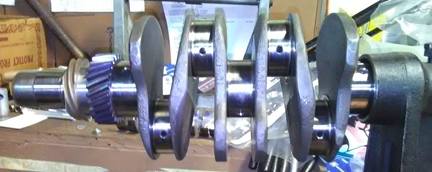
crankshaft is a genuine SC crank and was checked for cracks then polished, as
we do for ALL engines we build (unless it's a literally new crankshaft).
The
crankshaft is a genuine SC crank and was checked for cracks then polished, as
we do for ALL engines we build (unless it's a literally new crankshaft).
AT RIGHT: The crankshaft used in this engine - genuine SC and NOT a 912 crank! We'll give a $20 discount to any buyer who correctly identifies how you can tell (in this image) that it's an SC and NOT a 912 crank!
As usual, we rebuilt the connecting rods. These are correct for the SC and were used on all C, SC and 912 engines.
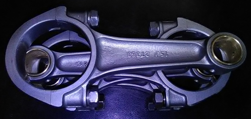
AT RIGHT: The rods in this engine - a very sweet set.
For us, "rebuilding the rods" means to:
 Resize
the big ends
Resize
the big endsThis is all standard work so there aren't any photos of them in-process.
AT RIGHT: We forgot to take a photo of this crank with the rods mounted on the crankshaft stand, so here it is resting on the foot of the engine stand, about to be laid in the case.
 In
the trial assembly, everything went normally, so time to button it up... But
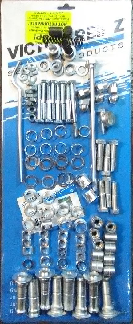
first, I rounded up all the hardware. I don't usually post an image of the hardware,
but it's all plated, and I thought it'd be nice to document it for posterity.
In
the trial assembly, everything went normally, so time to button it up... But
first, I rounded up all the hardware. I don't usually post an image of the hardware,
but it's all plated, and I thought it'd be nice to document it for posterity.
AT RIGHT: The hardware used on this engine:
At the top you can see the oil pressure relief pistons, their springs (not plated to avoid risk of hydrogen embrittlement) and plugs.
Then, there are the seven case washers and the "through-bolt," along with a pile of washers, nuts, and parimeter bolts, and on the left, the oil pressure control piston's back-pressure relief tube that prevents hydraulic lockup of the piston.
Then, there are the case-half acorn nuts, and below them the camshaft end plug, and bearing dowel pin / bolt for Bearing four (in the timing cover).
Following that, we have the valve-related hardware, including the stand mounting bolts, rocker shaft springs, "hats" and shims.
Below the hats are the shaft retainers over which the nuts go.
Below the camshaft end plug are the 6 special rocker stand mounting bolts.
Then, there are the upper head nuts followed by a row of the special head nut washers, and then the lower head nuts...
Very Sharp Eyed readers will note that ONE of the upper head nuts is longer than the others and doesn't have a groove down the center! This is an early one - I keep a few on hand. They're longer because they don't take the 2mm washer below them like the later ones do. And, because of their length, they can help solve problems sometimes when heads have been flycut because the nut has to receede so deeply onto the stud, there can be no room for the hex wrench! This longer length helps solve that problem which is why I keep some on hand, just in case! None were needed on this engine, though.
BELOW: Jumping ahead a little; the left half, trial fitting everything...
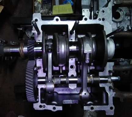
... So, As this is an SC engine, the most awesome of the 356 pushrod engines, I wanted to make certain everything inside the case is nothing but awesome. So, I selected a camshaft that is very close to what Porsche itself fitted, only maybe a tiny bit better: It's a "Web Cam", a tiny bit "hotter" than stock, a little bit more lift - ground onto a wide-lobe billet. It was then parkerized (see note on parkerization below).
The camshaft is the "brain" of the engine. This one will provide a good idle, it's not radical, yet it will take a little bit better advantage of the increase in displacement afforded by the big-bore piston & cylinder set. This engine, in proper tune, and when fully run-in, should get an honest 120 to 125 hp DIN - we know this because we have a dynamometer and test engines regularly.
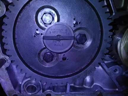
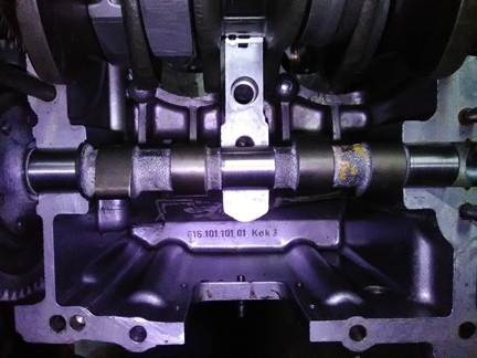
BELOW, LEFT & RIGHT: While these images were taken later, they show the cam designation (left) as an R0200.5 billet with a Web Cam grind on it. And, you can see the parkerization (the blackening on the lobes) in the image at right.
To go with that nice cam we fitted some nice original cam followers.
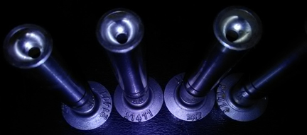 The
cam followers were refaced, of course, and the stems polished - as usual - though
they're not yet installed in this image at right.
The
cam followers were refaced, of course, and the stems polished - as usual - though
they're not yet installed in this image at right.
AT RIGHT: The ATE 21411 lifters are a bit uncommon, but that's what this engine came with.
The cam came without a gear, so I picked one out from this selection I have.
AT RIGHT: A while back I paid a gear-maker to size my 356 camshaft gear collection. Here they all, sorted by size, ready for use. This is really great to ensure a perfect fit every time!
Once it was all ready to go, the case halves were assembled, with this result:
 Pistons
and Cylinders
Pistons
and CylindersOriginal SC / 912 cylinders originally fitted to SC engines did not last as long as their all-iron counterparts because in the process of manufacture, as the aluminum fins are cast on to the iron, the iron is anealed, making it softer, and so they wear faster. In the modern era, several manufacturers are making replacements that are also aluminum fins over iron cylinders and they share the same wear issue, but at least they're current manufacture! And, all of these of which we are aware are also "big bore" (86mm instead of 82.5).
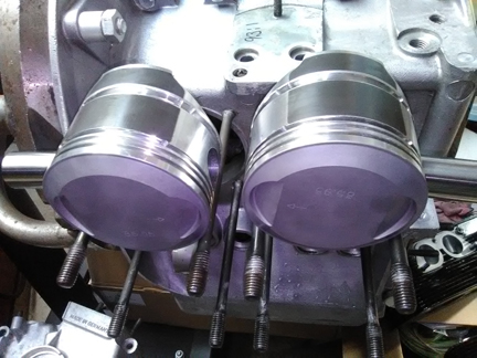
AT RIGHT: A pair of pistons which are going into this engine. They are big-bore (86mm), high compression (9.5:1) pistons fitted to biral cylinders (aluminum fins cast over iron). This is effectively a stock SC set, but with larger displacement. You'll see more of the cylinders in other images here. Note that the rings are removed during this phase of assembly and are only reinstalled during final assembly. ... Alert readers will spot the timing cover in the lower left; note how there are no numbers stamped in! And, a head can be seen lower, right. Finally note that at the time this image was taken, the Compression Ratio was determined and written in ink on the oil cooler mounting flange (9.3:1)
As noted above, these cylinders share the same wear problem as the original birals. Way back in the early 1950s, Porsche commissioned the vendor Mahle to make all aluminum cylinders and plate them with chrome, but chroming of aluminum was expensive, so later Porsche opted for aluminum fins cast onto traditional iron "liners" as a cost saving measure.
We always check the match pistons to cylinders and match piston weights as a set, and provide any remedial action to correct any errors before installation. For example, by shuffling around the piston pins among the pistons, one can usually improve the matching of piston weights. This set naturally balanced (without removing material) to within 0.3 gram - the official specification is ten grams (10g). This is attributable to the piston manufacturer - they are very precise!
 For
many shops, from this point, installation goes very quickly, but we think this
is where one needs to take one's time! DON'T RUSH!
For
many shops, from this point, installation goes very quickly, but we think this
is where one needs to take one's time! DON'T RUSH!
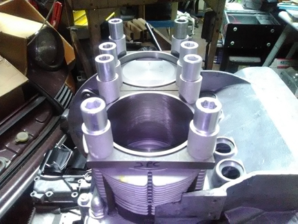
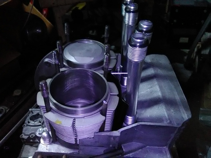
AT RIGHT: The right hand side cylinders (1 & 2) are about to undergo an installed Cylinder Height Check - or CHC, as described in the text. Note how the cylinders are retained with special spacers - these permit the cylinder to be held flat as it will be run in service and a check can be made to ensure that both cylinders top surfaces are in the exact same plane. The book value for tolerated error of installed cylinder height mismatch is 0.1mm, or four thousandths of an inch - the worst on this engine was less than three. ... Alert readers may notice this engine stand is next to a Porsche 911! ... We've gotten some new engine stands and have run out of room in our traditional engine building area!
The key reason one needs to take time here is that there are production tolerances on every part in an engine, and while a set of parts may look identical, there's often subtle variation between members of a set, and there are sometimes significant errors in production that weren't caught by the manufacturer's quality control processes. These errors can "stack up" and cause problems if not discovered and corrected.
Here's our process: Two of these steps require special tools most shops don't have.
 Take
a preliminary measure of each cylinder's height.
Take
a preliminary measure of each cylinder's height.We like to carefully measure everything and then mix-and-match the parts for superior fit. We have also discovered significant manufacturing errors with this process which would likely have gone unnoticed without these measures. It is remarkably easy, for example, to overlook the circumstance of the crankshaft bore not in the true center of the crankcase, angled on the horizontal left or right of center, or not on the same horizontal plane at all. Yet examples of errors like these are not as uncommon as we would like.
AT RIGHT: The left cylinder pair undergoing CHC. Note how the nut spacers are beveled such that they do not touch the cylinder whatsoever for a true reading. This tooling is for three-piece cases; we have another set for earlier two piece crankcase engines.
The methods by which we accomplish these steps involve steps nobody else does (that we know of) in the engine building process, and that is to measure the height the piston crown comes above the plane of the top of the cylinder. I call this the CAC, or "Crown Above Cylinder." This value is important because, firstly, it can reveal deeper problems, and because it helps us get the compression ratio equal in all four cylinders.
AT RIGHT: Cylinder 2 undergoing its CAC.
Here are some of the deeper problems that can be discovered through a CAC check:
 An
improperly ground crankshaft
An
improperly ground crankshaftAT RIGHT:Cylinder 1 having its CAC value measured. All four cylinders are measured this way, and should any significant difference be found between cylinders, swapping pistons, cylinders or even heads around can help make a better compression ratio match - or simply find out exactly where any discrepancy may lie for remedial action, as necessary. This measure is extraordinarily accurate - we always find differences on cast pistons, and even forged pistons are not immune from production tolerance differences.
In order to do this for these engines, you have to have special tools. Here, you can see them in action on these images which document the "CHC" and "CAC" steps.
 The
distance between the smallest tick marks is one hundredth of a mm, or 0.0004",
and you can discern to perhaps a tenth of that! So, this is a very accurate
measure, performed while the cylinder is under torque, so any shims are squished
flat, etc. In terms of the CAC value, it is better to consider its effect on
combustion chamber volume rather than thinking of it as a length.
The
distance between the smallest tick marks is one hundredth of a mm, or 0.0004",
and you can discern to perhaps a tenth of that! So, this is a very accurate
measure, performed while the cylinder is under torque, so any shims are squished
flat, etc. In terms of the CAC value, it is better to consider its effect on
combustion chamber volume rather than thinking of it as a length.
AT RIGHT: Everything is all set for the mounting of the cylinders at this point. This particular engine stand is primarily for 911 service, and doesn't (yet) have a tool / parts shelf attachment like most of our other engine stands have. And so, the ring compressor is in the foreground left, on top of a cylinder head... We have designed a custom shelf for this stand but haven't fabricated it just yet.
The accuracy of this measure is so good, that if you take the time to swap parts around, you can accurately determine discrepancies in the manufacture of the various parts! But, we ARE splitting hairs here! However, a benefit to both engine builder and customer is that the ability to move parts around for better fit means that perfection is more easily achieved, and the more equal the HP production of each cylinder, the smoother the engine will run, and the more HP the engine will produce overall.
Because this process includes the entire assembly, torqued as in service, and measures the height each piston protrudes out of its cylinder, any and all errors in connecting rod lengths, cylinder heights, crankcase spigots depths (cylinder bore deck), piston connecting pin heights, and shim thickness' are accounted for in the measurement results. There is no superior method.
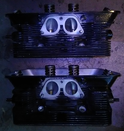
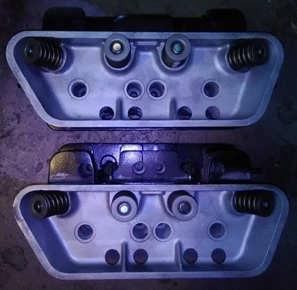
As knowledgeable people will know, SC heads were originally coated with a black coloration to aid in heat disipation. As noted on the web pages describing other SC engines we've built, the original coating is not very durable. In this instance, it looks as though someone has touched-up the black coating on these heads - we didn't do it! But we think it was a reasonable job, so we left it alone. Also as stated elsewhere, our goal is to have a consistent, reliable product, so (as with all our engines) we replaced all the valve guides, used new higher-tension springs, re-faced the valves, ground & lapped the valve seats, and then carefully assembled the valves onto the heads paying special attention to spring-heights. The exhaust valves used here are genuine sodium filled parts, as original on SC (and 912) engines.
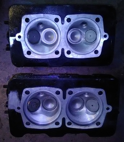
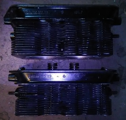
BELOW LEFT & RIGHT: The heads, ready for installation. No broken fins. No loose bits have been through the combustion chambers! And, they've been flycut and decked, including a conical cut to help restore original combustion chamber shape after flycutting. ... Worth mentioning: We always pay attention to the threaded bores on the heads and in this instance, two received thread-repair, including one exhaust stud and one intake manifold bolt hole. The rest were fine.
A small point about the valves: They're great originals, not aftermarket replacement which are all you can get new today. Further, and vitally, the exhaust valves ARE the sodium filled type, which haven't been available new for some years now. Of course, the valves have been checked for length (stretching makes them unworthy), refaced, and stems polished, so they're effectively perfect.
We recently went through a batch of about 32 new springs and they were grouped by strength. We match up slightly stiffer springs with the heavier valves (intakes are about 2% heavier than exhausts), so they're very close sets, matched up, so all the valves tend to float at the same time. ...Of course, each valve and retainer are position-specific through the shimming process as the spring-heights are set. This close-matching of spring tensions helps the driver know when they're over-revving because all the valves will tend to float at exactly the same time, thus sending the clear signal of a drop-off in power. When one or two valves float before the others, the driver may not realize they're harming the engine and continue on, getting into trouble!
The springs are also a bit stiffer than stock. The stock closing pressure was about 68 lbs, but experience has shown that sometimes when someone might over-rev the engine, a piston can strike an exhaust valve with very negative consequences. Modern professionals know this and install stiffer springs.
 At
this point the engine is ready for its cylinder heads, and this work went very
quickly - as it should! - as all the prep work was already done. A long time
previous, back when we were getting the case halves ready, we already sorted
out the head "bolts" and washers, prepared the pushrod tubes, prepared
the lower cylinder air deflection plates and their wire retainers. The torque
wrench was already set, so bolt on those heads!
At
this point the engine is ready for its cylinder heads, and this work went very
quickly - as it should! - as all the prep work was already done. A long time
previous, back when we were getting the case halves ready, we already sorted
out the head "bolts" and washers, prepared the pushrod tubes, prepared
the lower cylinder air deflection plates and their wire retainers. The torque
wrench was already set, so bolt on those heads!
My pattern is to mount one head, torque it to 72 inch lbs, then mount the other head the same way, and then alternate between the heads with an ever-increasing torque up to the final torque value, then repeat the final torque value until the fasteners no longer turn when torque is applied.
At this point, I often will have mounted the timing cover before now, but for whatever reason, it wasn't.
BELOW LEFT & RIGHT: The engine before the timing cover was installed, then after. Sorry, no image was taken before the oil pump was installed!
To accomplish this, the bearing was marked with ink where the dowel goes so it can rotationally be aligned, then the case is marked on the inside where the bearing dowel is so it, too, can be seen (see image below). Then, the bearing was left in a freezer for a long time, I then sparked up the old O'Keefe & Merrit oven and heated the timing cover to about 225 - 250 F, set up the jig to catch the bearing should it fall through and installed a new nose bearing (#4). ...I'd forgotten the steel-backed bearings don't shrink as much so it only went partially in before sticking, so I pressed it the rest of the way on - typical fare.
 Of
course, during the case preparation phase, the timing cover was cleaned, and
was gently "lapped" on our inch-and-a-half thick slate lapping table,
mostly just to help ensure it's flat and clean on the sealing surface. Here,
you can see the timing cover ready for assembly, then installed.
Of
course, during the case preparation phase, the timing cover was cleaned, and
was gently "lapped" on our inch-and-a-half thick slate lapping table,
mostly just to help ensure it's flat and clean on the sealing surface. Here,
you can see the timing cover ready for assembly, then installed.
AT RIGHT: The timing cover just before installation. Note the ink marks on the bearing and case indicating where the dowel is located. This side gets the oil pressure control piston's vent as well - the long tube with red grommets at the ends! You can also see the light markings in the case from the lapping process described in the text.
As soon as the timing cover was mounted, in goes the splash washer that protects the oil seal, then the pully's woodruff key, then the pulley seal. Next, the oil pump drive gears, already thoroughly cleaned and the drive key attended to, were oiled up and the pump cover installed.
Then, I attended to the oil sump studs - three were missing. On this occasion I installed three bolts of the right length from the inside - quick, easy, done.
The oil pressure control piston went in next, oiled up of course, then the spring, seal and cap - the second oil control piston was already installed in the left case half.
At this point all that's missing is the valve gear.
I used a special tool to measure any discrepancy in the head "bolt" mounting heights and, indeed, one was found to be low by about 0.35mm. A shim was located, problem solved. If this is not attended to, and all too often result is a cracked rocker stand! I have seen many in my day! I'd say, as a guess, that at least one in ten is cracked, and I've seen engines with TWO cracked stands! ... My perception is that most "mechanics" neither know that this height is vital, nor do they check the stands for cracks...
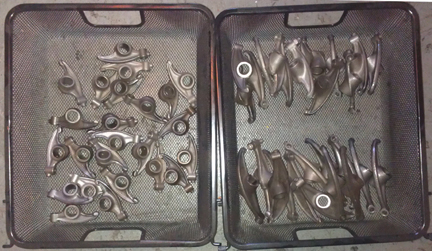
As attention is then turned to the rocker gear, as stated elsewhere on this page, we take special care to do a really great job, and one detail that is very often overlooked are the rocker arms where they contact the valve stem.
The late type rockers, as first used on the S90, then on the C / SC, and 912 engines, were surface hardened by the factory, but once that's worn through, the rate of wear goes up considerably and metal particles get introduced into the engine oil. By now, they're virtually all worn through the hardening and have this problem. Therefore, we hard-face every rocker. In this process, new material is welded on to the rocker's valve contact face and then the face is re-machined to the proper curve and smoothness. This not only repairs worn out rockers, but it's also a bit better than stock, too, because the "hard face" material is super tough, harder than the original rockers were.
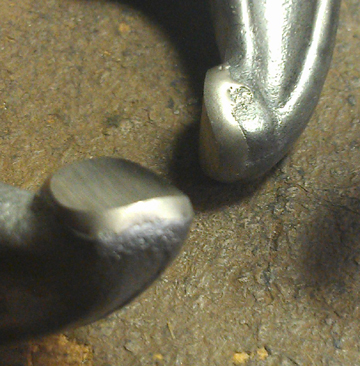
BELOW LEFT: Larger than real-life close-up showing the new material having been applied to the rocker's contact faces and then properly ground. These rockers won't wear like the originals did - this should be a "lifetime fix" for most engines! And, it also helps lengthen the life of valves by reducing wear on the valve stem caused by an uneven rocker contact face.
BELOW RIGHT: Yes, doing them in large batches is MUCH more economical. This is about seven engines worth. We do several batches a year - this image was taken a few batches ago, but they all look pretty much the same!
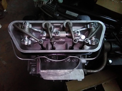
A SMALL point, but important: EVERY engine gets all new valve adjustment jamb nuts!
BELOW: Here you see the late rockers installed - we think the plating on all the hardware is a nice touch! But it's not just bling; we also attended to the rocker arm contact faces as described above...
Finally, the flywheel, a new 200mm unit!
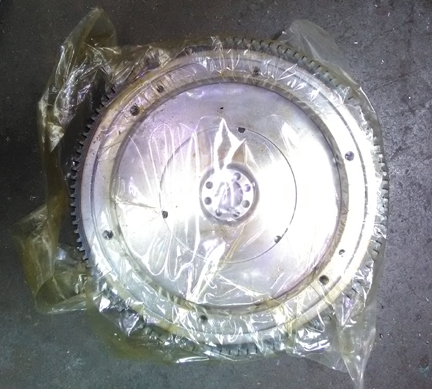
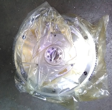
And now here it is as the longblock, ready for pickup or delivery! (Two images of it finished are up at the top.)