Copyright © 2007 - 2025, Coachworks For contact data Click Here.

Copyright © 2007 - 2025
Copyright © 2007 - 2025,
Coachworks For contact data
Click Here.

The following was sent to the Karmann Ghia Club of North America's email list on August 224th, 2009:
...When we last left off our saga, the big question was CCing the heads. That
is, even though the term CC means cubic centemeters (same definition as a milliletre),
and even though CCing would seem to mean measuring the volume, most engine builders
use the term to mean making the combustion chambers match. And recall from our
last installment that I was rather annoyed that the one intake valve with a
new valve seat was "sitting proud" - more deeply into the combustion
chamber than its neighbor - and thus throwing off the two chambers from matching.
I was looking to vendors to help, like Buggy House in Hayward.
However, I was in the role of Dorothy; I already had the ruby slippers that
would bring me home!
Yes, a good friend had given me a valve seat grinding tool set - free! - and
the stones that came with it were too large and it was a weekend, so there was
no buying smaller ones. Well, I'm _glad_ it was a weekend as otherwise I might
have spent money I didn't need to spend. You see, I spoke with the guy who installed
the particular valve seat in question and he said, "Hey, didn't you get
the stone dressing tool with that setup?" Well yes... "...They usually
are designed to let you do everything you might want to do to a stone, including
reduce its diameter..."
 Doah!
He Was Right! (hence the ruby slippers...)
I set out the tool in a suitable environment (it generates lots of hard dust
that's dangerous for machine parts), played with the mechanism until I understood
everything about how it worked and what it could do and proceeded to cut a set
of stones to fit this application. It worked great!
I then proceeded to cut the too-new seat so it was deeper, more like its older
neighbor. ...REMEMBER, can't go too far or you'll regret it! "Can't Put
The Metal Back!" Well, cut it as far as I felt prudent, measured the CCs
and found it was _just_barely_ short of enough. As grinding valve seats involves
three different angles and alters the depth of the valve head - which has a
very large influence on the volume of the combustion chamber - I felt it safer
just to grind out a little more material using a carbide burr... And so, two
little buzz-and-measure sessions and I had it Spot On The Nose PERFECT! Yea!
I promptly stamped the combustion chamber volumes into the webbing between
the cylinders (for future reference) and proceeded to mount the cylinder heads
on to the already assembled and patiently waiting bottom end. This meant not
forgetting the air deflection plates below the cylinders, along with the more
usual installation of pushrod tubes. In this case, there are special "head
bolts" (really special head _nuts_ would be more correct) that are used
in equal-length head stud assemblies, and these have o-rings that seal them
where they protrude through the "rocker chamber" (aka "rocker
box") toward the ends of the head-nuts. I had two choices; early, without
extra washers, or later, with. I chose the early ones because there are fewer
small parts to lose if I have to take it apart while out at Bonneville, Dog
forbid.
I first torqued the heads using the 7 foot pounds patern, first one side, then
the other. And then I alternated from one head to the other, upping the torque
on the fasteners in 5 foot pound increments. I like to do this because it permits
the stresses from one side of the crankcase to be "transmitted" through
the case to the other side a little at a time, while there's still more torquing
to do, and thus there are neither over nor under torqued fasteners when completed.
...I repeated the final torque three times. As an aside, this procedure meant
swapping out two different tools on the torque wrench a total of FOUR times
per single torque value for a total of fifty six wrench changes! Yes, tedius,
but required because the upper inner head studs (the "intake studs")
require a different fastener than the others (15 ATF versus 10mm hex socket
- ATF means "across the flats").
OK, heads mounted! Now on to the valve train!
 I
knew I'd have to make pushrods, but I have a set of originals (that I don't
want to use), so I started with them. I then assembled and installed a rocker
shaft and was _very_ disappointed at the geometry. Investigation proved, however,
that there were at least two improperly machined rockers! Yikes! What I should
say is that at least two were machined differently from the rest and they didn't
like this particular length of pushrod _at_all!_ Luckily, I have several sets
and so I pulled out parts that fit and work correctly.
 I
then measured the length of the pushrods and got out the cores I was going to
use to make new custom length pushrods from. I tried to fit the parts together
in my hands, just playing like a 4 year old, and I found that the sockets on
these rockers are too deep and will not accept standard pushrod tips! No Way!
Oh, they'll go in alright - they use the same diameter / radius of tip, but
they "lock in" to the sockets and do not have sufficient range of
motion.
If I had not had some original pushrods I'd have been completely lost as to
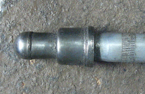
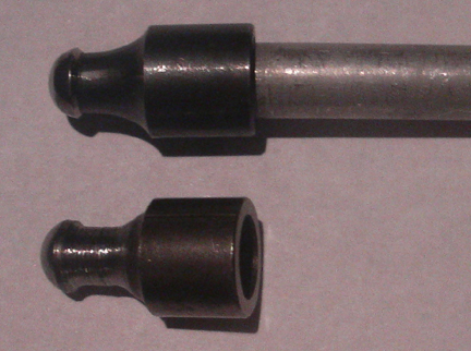
what was going on. However, the original parts are deeply undercut just behind
the contact point, unlike other VW pushrods. I looked at early Porsche as I
have some of those on hand also - nope, they weren't undercut either. ...It
then came back to me - the words of Richie Lukes of famed Lukes & Shorman,
the original Porsche racing mechanics from the 1950s; "The pushrods used
to pop out of the sockets when you were on it really hard, usually at just the
wrong moment! ... We'd just pit, pop the valve cover and pop them back in place
and keep going!" ...So... Denzel was eliminating this possibility by providing
a very deep socket, but to make it work, the pushrod tip had to be clearanced
to provide the necessary range of motion. ...Further study showed that circa
1960 - with the advent of the "light alloy" rocker stand, Porsche
too moved to this type of design, fully 10 years after Denzel!
Great. Now what?
 I
went to my stash of old VW parts and found some early 25/36 hp lifters which
have the integral pushrod, specifically seeking out those with completely wiped
out contact faces where the lifter contacts the camshaft. These would be no
good to anyone but someone like me, looking to make pushrods! _Some_ of these
parts had a tip that looked like the Denzel, though they were not undercut.
I thought, hey, these are hardened, even if I had a laythe in good condition,
these aren't going to be cut very easily on a laythe. Also, they have a radius
to them that would also be difficult to do without making a special cutter.
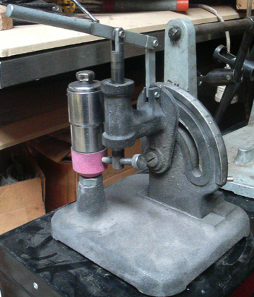
It then dawned on me - grind them! So, I fabricated a tool to remove the pushrod
tips and removed 8 or so - and along the way found that the pushrods were filled
with wooden dowels to take up their inner volume. This was done to help get
oil up to the rockers at startup a bit faster. These dowels will, in time, clog
the oil passages as they decay, putting wood bits into the oil and keeping oil
from getting to the rockers. I say omit the buggers and just wait a little longer
at startup before you put your foot in it.
I
went to my stash of old VW parts and found some early 25/36 hp lifters which
have the integral pushrod, specifically seeking out those with completely wiped
out contact faces where the lifter contacts the camshaft. These would be no
good to anyone but someone like me, looking to make pushrods! _Some_ of these
parts had a tip that looked like the Denzel, though they were not undercut.
I thought, hey, these are hardened, even if I had a laythe in good condition,
these aren't going to be cut very easily on a laythe. Also, they have a radius
to them that would also be difficult to do without making a special cutter.
It then dawned on me - grind them! So, I fabricated a tool to remove the pushrod
tips and removed 8 or so - and along the way found that the pushrods were filled
with wooden dowels to take up their inner volume. This was done to help get
oil up to the rockers at startup a bit faster. These dowels will, in time, clog
the oil passages as they decay, putting wood bits into the oil and keeping oil
from getting to the rockers. I say omit the buggers and just wait a little longer
at startup before you put your foot in it.
So... I left 8 pushrod ends on their pushrods and merely cut the lifters off
and I removed 8 ends - and a few spares for an oops or two - chucked them in
the laythe, spun them backwards to my hand-held grinder (that I usually use
to grind welds), and set about under-cutting the tips as per my example original
Denzel parts.
It worked! They're not as pretty as the original Denzels but they're nice enough
and have this definite hand-made quality about them!
Now, to make the pushrods, I want the length perfect, so I have to make sure
the rockers are exactly in place where they go, so I turned my attention to
the rocker shafts. They take the same parts as VW - or so everyone thinks. However,
not so! The side-thrust alignment pieces must be of a different width and I
didn't have any originals. So, I made some. I used 1/2 inch electrical conduit
galvanized steel tubing. I took a part used to join two lengths of such material
and made it into a precision measuring device - it can slide along the length
of the pipe so you can make a precision mark just where you want it. I cut some
lengths, chucked them in the mill and drilled some holes and then cut a slit,
all as original in design, and then de-burred the material with a couple of
different hand-files and finally lapped the lengths to fit. They work wonderfully!
Now the valves are held at the right distance apart...
Meanwhile, the calendar keeps ticking off days and I have to get the next coat
of paint on, so, each day in the early morning light, I've gotten out there
and looked for and marked every flaw I can find in the paintwork. They're pretty
much all found now. Today I sand the low spots and apply "catalyzed glaze
compound" as unlike plastic body filler, it can be applied over paint.
After it hardens, I'll sand smooth all the spots and hopefully that'll be it,
but as a confirmation, I'll paint the areas with high-gloss black rattle-can
paint! This will help show _all_ remaining flaws in the paint. When Done Fixing
Them All (he says hopefully!), I'll then give a final light sanding to the entire
vehicle where more paint is to be applied. And then tomorrow we shoot the car
_again!_
I should have time today to finish the pushrods, do a valve adjustment, and
mount some valve covers!
...Hope you're finding all these keystrokes of interest!...
Images here:
https://ghiacoachworks.com/share/denzel_lsr.html
Richard