Copyright © 2007 - 2024, Coachworks For contact data Click Here.
Copyright © 2007 - 2024
Copyright © 2007 - 2024,
Coachworks For contact data
Click Here.
![]()
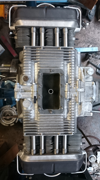
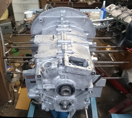
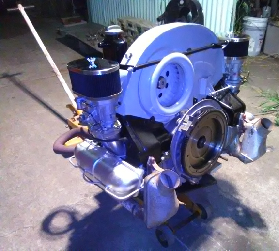
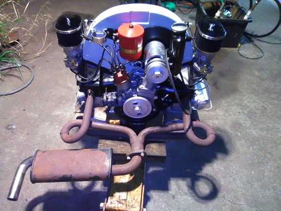
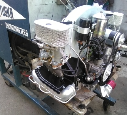
AT RIGHT: This photo was taken moments before the engine had the carburetors tuned on our Stuska Dynamometer. This is aproximately as it was when it was crated and shipped..
This 1966 Porsche 912 engine has just undergone a complete overhaul, and is fully balanced for smooth running, long life, and a few more HP. This page tells its story in 41images!
This engine has many standard features we apply to all our engines - such a long list, we'd bore you here, but they're fully descrbied below.
BELOW RIGHT: This engine, as a long-block, ready to go!
 On
This Page
On
This Page
This engine started life as a 912 engine, the case cast in 1966, and we first prepared it as a long-block, then decided to prepare it for use in a 1971 Karmann Ghia. However, when it actually sold, our customer asked us to prepare it for service in a 1961 Porsche 356 Roadster that had been fitted with 741 transaxle (with throw-out bearing guide tube) and 12v electrics.
Here are the implementation and / or conversion steps we implemented.
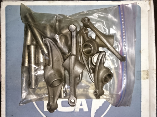
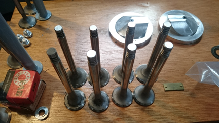
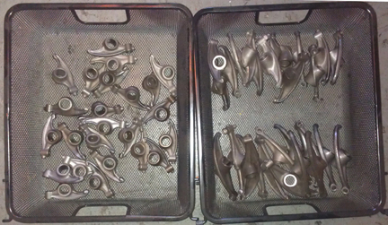
AT RIGHT: Here we have the rockers used in this engine ready for installation. They have been cleaned, and shafts polished, of course. Additionally, the tips which ride against the valve stems have been not just refaced but a new layer of metal has been added to help reduce wear. In the original, it was only surface hardened, and once worn through, the rockers won't keep adjustment - and keep shedding particles into the oil! However, this "hard-face" material is stronger than the original surface and is considered a permanent solution. There is a close-up photo further down.
 Background
on This Engine
Background
on This EngineThis 1966 engine came to us as a "core" and has just undergone a complete overhaul, and is fully balanced for smooth running, long life, and a few more HP.
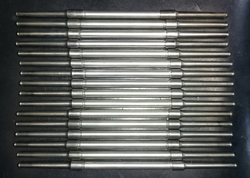
AT RIGHT: Two sets of pushrods, ready to go, one set of which went into this engine. Note that this type, with long steel ends and a short aluminum center, is for use with iron cylinders, like the NPR's fitted here.
This engine is type number 616/36 (912) and was originally constructed the summer of 1966. Of course this engine, as a 912 has all the features of a 912, often called "the late-type" in 356 circles, meaning that things like the oil pump, rockers, etc. are of the best (latest) design. This engine has undergone a thorough rebuild as described herein. Every detail about the engine has been attended to; nothing was ignored.
We received this engine among a group of cores bought at the Partsheaven swapmeet in the spring of 2015. Unfortunately, nothing further about this engine's past is known to us. However, during this rebuild it was fitted with new genuine NOS NPR 86mm cylinders, it received new rod and main bearings, all new valve guides, its lifters and valve rockers were refaced, etc., and even the plating of small parts was attended to, such as the wire bails that retain the valve covers and air deflector plates, the nose bearing retaining bolt, the through bolt, and so forth. Nothing was overlooked.
This one was torn down LONG before we got it!
 Crankcase
Preparation
Crankcase
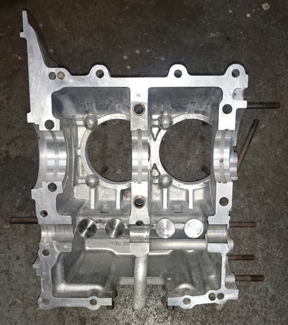
Preparation This crankcase just needed a good cleaning and thorough inspection. A few studs were missing. Other than this, the case looked great!
Inspection showed, however, that the case was align-bored to 61.5mm - an unusual size - and one bearing saddle appeared to have been cut a little too large. (This is likely the cause for why the case was dis-used.) So far as could be discovered, nobody ever manufactured a bearing larger than 61.5, but I did find a set that size. Luckily, the over-size bearing saddle was #3, and, because it's #3, you can make a bearing for it. So we did - you can see it in the photos during assembly.
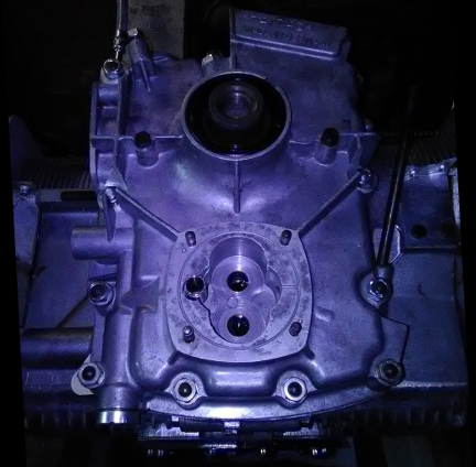
AT RIGHT: The crankcase with an initial cleaning, being inspected. There were two missing timing cover studs, a few missing oil pump studs and other minor issues. ... We usually photograph both halves, bare, top-down yet for whatever reason, those images didn't work out for this half (left - the right one is below). Instead, you can study the case in the photo below where the case is about to be buttoned-up.
A pair of studs were made to replace the missing timing cover studs, and the three or so sump studs were similarly replaced. A die was run over all the threads and the two sheet metal screw bores in the timing cover were checked and were found to be fine.
The various threads were then oiled.
No other damage was discovered.
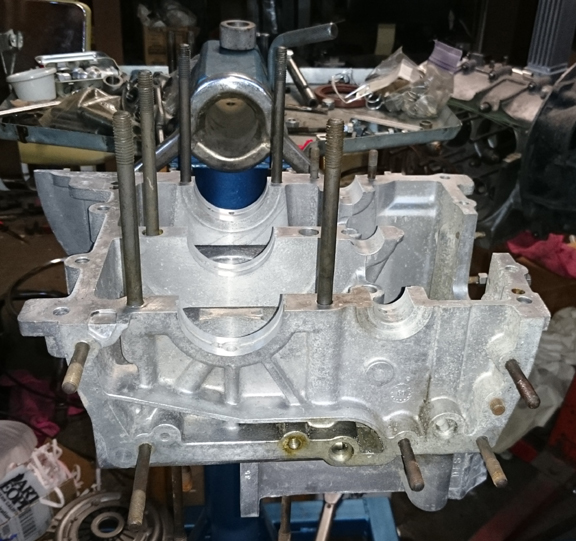
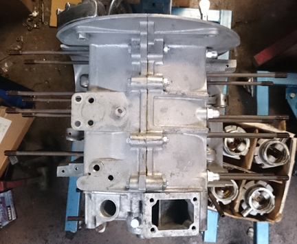
AT RIGHT: The right half, cleaned, inspected, threads chased, lifters installed and for case sealant! the only other thing needed before assembly is bearings!
 There
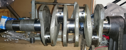
was no particular crankshaft that came with this crankcase so the one at right
has been provided. It's an "SC/912".
There
was no particular crankshaft that came with this crankcase so the one at right
has been provided. It's an "SC/912".
AT RIGHT: This crankshaft had formerly been magnifluxed and re-ground by famous engine builder Harry Pellow, and not used until now. It's been waiting around some 20+ years to be put into service!
AT RIGHT: To this were fitted appropraite rods, rebuilt as usual: Late type, the best ever made. We do rods in batches like this - here are 7 sets, 5 of which are the late type. It's cheaper to do rods in big batches...
For us, "rebuilding the rods" means to:
This is all standard work so there aren't any photos of them in-process.
Note that I usually photograph the specific set of rods that goes into each engine, but I was building two nearly identical engines side-by-side (the other one is 74596x, found here) and got a little confused about what I had or hadn't already photographed. So I don't have them for this engine, but they were one of the sets in the picture at right.
BELOW LEFT: Missing the usual photo on the crank stand, here's this engine's crank in the workshop freezer getting ready for the crank gears to be installed...
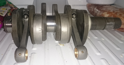
Also note I usually take a photo of the crankshaft with rods mounted, positioned in my crankshaft stand as it is being assembled, but somehow that photo was overlooked for this engine. However, you can see them mounted up in the photo above, in the freezer awaiting gears, or below showing the left case half with crank, ready for the right half to be mated.
 And
note, in the image at right, the remarkable variety of subtle differences in
the connecting rods. Porsche used several manufacturers and for whatever reason
most "sets" were mixed from different vendors and even different tooling
from the same manufacturers. In rebuilding a large quantity of rods as seen
here, I try and match them up better than Porsche did - BEFORE the rebuild process.
The result is less material has to be removed for balancing end-for-end and
in total weight.
And
note, in the image at right, the remarkable variety of subtle differences in
the connecting rods. Porsche used several manufacturers and for whatever reason
most "sets" were mixed from different vendors and even different tooling
from the same manufacturers. In rebuilding a large quantity of rods as seen
here, I try and match them up better than Porsche did - BEFORE the rebuild process.
The result is less material has to be removed for balancing end-for-end and
in total weight.
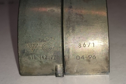
AT RIGHT: I don't usually bother to photograph rod bearings, but since I was missing the usual images of the specific rod set and them mounted on the crank on the crank-stand, ... here's a treet! These are actually genuine Porsche rod bearings - not something seen too often today!
 Crankcase
Assembly
Crankcase
AssemblyBy the time we get here, the case has already gone through cleaning and whatever machine work it may need, so here we should be ready to just assemble it all!
This usually goes pretty quickly - if all the previous tasks were performed correctly.
AT RIGHT: The left case half now ready for assembly, with everything ready but the camshaft end-plug - see that below! Note that the lifters have been refaced - never assemble an engine without refaced (or new) lifters! (Four of the lifters are in a photograph above installed in the left case half.)
At this point, one merely confirms everything, double checks most of what one thinks one knows about the assembly and then fits a cam and its gear. These are the last steps before buttoning up the bottom end...
The camshaft is a very low mileage original wide-lobe replacement - note the lack of wear on the camshaft end in the image below.
BELOW: While assembling this engine (and its stable-mate, 74596x), I happened to notice that there were two types of the same type lifter! What?! Take a look in this image of the back-side of the lifter heads of the two versions of the same type lifter. Note that one side has the "Ate" logo and 3900 designation upside down as compared with the other one! Both were part of the same original set!
The next step (already done in one of the images above) was to find a gear for the camshaft. They're sized of larger or smaller than a standard just called "zero." The range of available gears back in the day was maybe +3 to -3 from Porsche (or VW) and perhaps as big as +5 and small as -5 from aftermarket sources.
Today you're lucky if you can find any! However, over 30 years ago now I bought up a stash of twenty or so new gears to add to my small stash. Generally one comes in when another goes out, but occasionally a new one or so gets added. So, there is some modest churn in the stock. But what I have learned is that the gears weren't consistently marked between vendors, so one vendor's +1 might be another vendor's -2. Strange but that's how it is. So, you have to constantly pick through gears as a trial-and-error process rather than just grabbing the next size over. Another fact is that for some reason, every engine seems to need a negative 1 or smaller. So, all the really small gears get picked over and all that's left are larger ones.
AT RIGHT: The box of properly sorted cam gears as discussed in the text, ranked by size (paper tags).
This makes it crazy-hard to quickly select a cam gear that fits. So, a year or so ago, I contracted a gear company to take my stash of some 25 or so units and rank them by size and then trim the really big ones to fill in the gaps on the small end of the scale. So, in this instance, I found the right gear on the second try! The first one had no lash, so I went two smaller and PERFECTION! I like it when that happens! And it has happened very frequently since I had then re-sized and sorted!
With the cam selected, gear fit, now time to put the case halves together! (Note the other case half was waiting and an image of it is found above in the crankcase preparation section.)
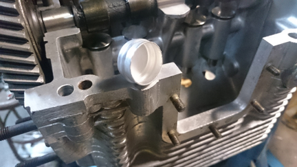
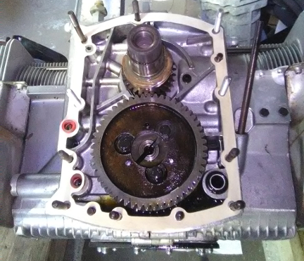
AT RIGHT: Here, the cam's end, with gear mounted, close up. Note that there is NO wear in the oil pump drive slot (the dead center), which just goes to show how little service this cam had seen previously. (These slots on used cams are nearly always damaged. It's usually modest, but noticeable.) Note also that dowels were not fitted. Older cams were always doweled, but younger ones were typically not, and it doesn't matter as these days we use "Loc-tite" or similar adhesive paste which was not available back in the day.
Assembly of the two halves then goes rather quickly and the result is a "bottom end," sometimes called a "short block" - sometimes a short block doesn't include the timing cover, sometimes it does!
In this instance, once we knew which main bearings were being fitted, we installed the new nose bearing into the timing cover. Unfortunately, that process requires working quickly as the cover is heated in an oven and the bearing left in the freezer, then they're put together before the temperatures equalize - no time for photos! However, given experience which has proven it necessary, our strategy is to set up our special jig that catches the bearing from falling through.
 AT
RIGHT: Another item seldom photographed is the camshaft end-plug. We plate
ours when there's the opportunity, as seen here. This image also gives a good
view into the left case half...
AT
RIGHT: Another item seldom photographed is the camshaft end-plug. We plate
ours when there's the opportunity, as seen here. This image also gives a good
view into the left case half...
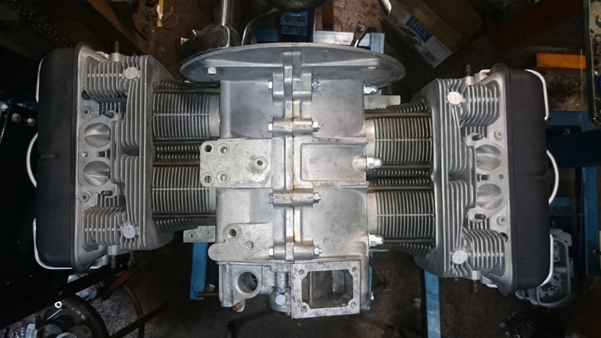
At this point, original Permatex brand "Aviation gasket" case sealer - the original type used by both VW and Porsche - was applied, the case halves mated, and torqued, and we have then what's called a "short block" - an odd name given that Porsche engines don't have "blocks", they have "cases!" In any event, in the three-piece crankcase world, a "short block" may or may not have a timing cover installed...
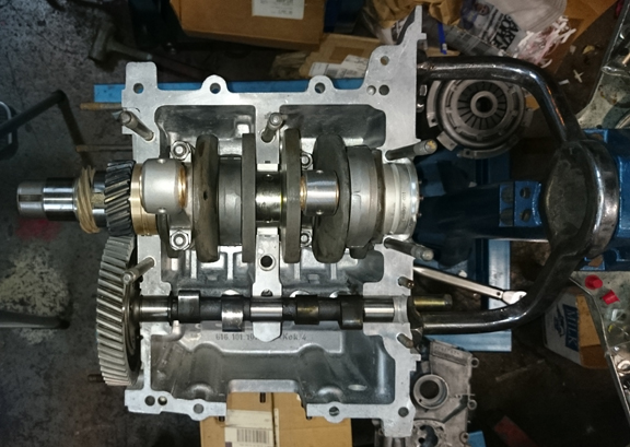
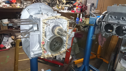
AT RIGHT: The engine is now in "short-block" form and timing cover seals and gaskets installed, as well as the two timing cover replacement studs discussed above in the crankcase prep section. You can also note that all the nut-and-bolt hardware is plated... Sharp viewers will notice yet another, very similar engine going together in the background.
Here, we'll just let a few more images do the talking as we get to the installation of the timing cover... (...How many other engines being assembled can you spot in the background here?)
TIP: Adjust your browser so that the "short block" images below are side-by-side - it was the width this page was "designed" for!
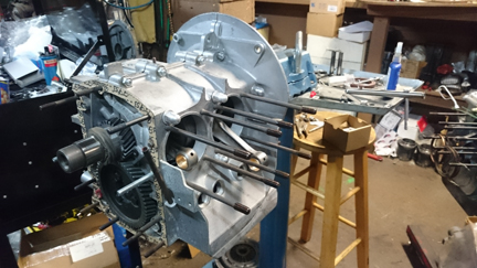
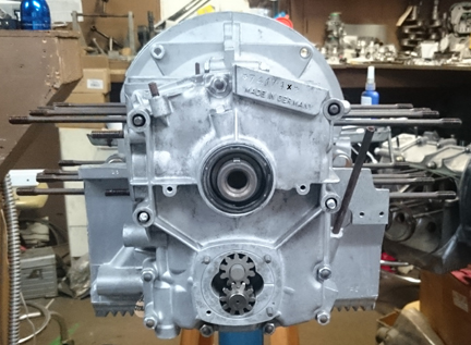
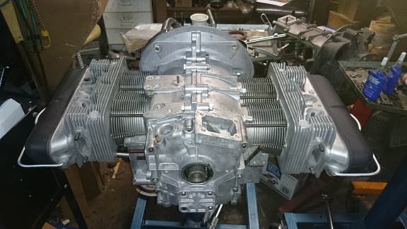
AT RIGHT AND ABOVE: Here, the timing cover has just been installed. It, too was carefully inspected and cleaned. The sharp reader will notice the nose bearing retaining bolt has also been plated. The oil slinger, seal, and pulley key were all promptly installed. The oil pump gears, previously cleaned and the drive end checked, were then installed. Shortly after this, the oil pump cover was installed. ... Note that the pistons and cylinders are visible in a box on the right side of the image immediately at the right.
I think it's pretty!
The engine is now, ready for the next stage; conversion from short-block into a long-block!
 We
selected for this engine a set of the new-to-market AA brand pistons and cylinders.
They offer a variety of choices. In this instance we got the biral cylinders,
which are an original type of manufacture for SC and 912 engines, like this
one, so we like that. This technology casts aluminum, which has a very high
coefficient of thermal conductivity, on an iron cylinder, notable for durability,
resulting in a cooler-running assembly.
We
selected for this engine a set of the new-to-market AA brand pistons and cylinders.
They offer a variety of choices. In this instance we got the biral cylinders,
which are an original type of manufacture for SC and 912 engines, like this
one, so we like that. This technology casts aluminum, which has a very high
coefficient of thermal conductivity, on an iron cylinder, notable for durability,
resulting in a cooler-running assembly.
The piston is effectively a copy of the rather famous NPR design that was the first "big bore" available for the Porsche 356 and 912 engine series. It's a cast piston with a 9.0:1 nominal compression ratio. We balanced the pistons to 0.1 gram.
A little unsure of a new product, I gave them a try in one of my engines and put about 2 thousand miles on them. They make good power and I was happy enough.
For many shops, from this point, installation goes very quickly, but we think this is where one needs to take one's time! The key reason one needs to take time here is that there are production tolerances on every part in an engine, and while a set of parts may look identical, there's often subtle variation between members of a set, and there are sometimes significant errors in production that weren't caught by the manufacturer's quality control processes. These errors can "stack up" and cause problems if not discovered and corrected.
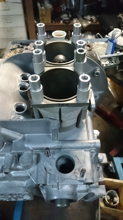
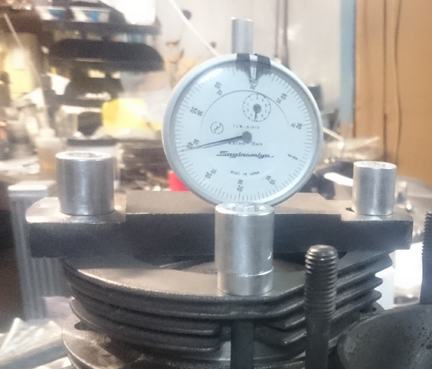
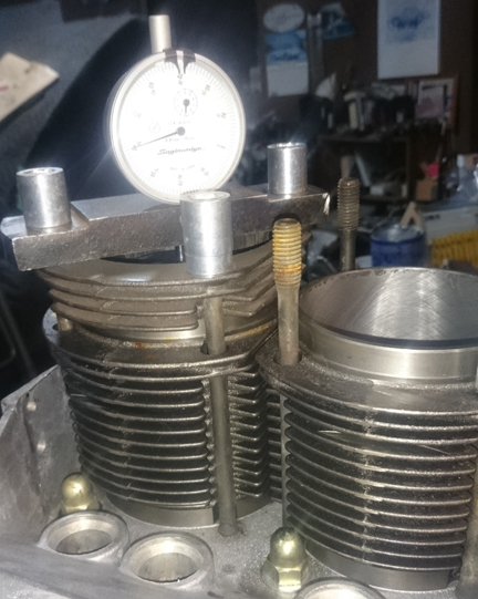
The next thing we do is something nobody else does (that we know of) in the engine building process, and that is to measure the height the piston crown comes above the plane of the top of the cylinder. I call this the CAC, or "Crown Above Cylinder." This value is important because, firstly, it can reveal deeper problems, and because it helps us get the compression ratio equal in all four cylinders. Here's our process: Two of these steps require special tools most shops don't have.
ABOVE RIGHT: The cylinders were then trial-fit into their bores in the case and retained with special tools to measure the installed cylinder heights and ensure they match their neighbor. This is the CHC, and both sides are done.
The accuracy is so good, that if you take the time to swap parts around, you can accurately determine discrepancies in the manufacture of the various parts! But, we ARE splitting hairs here! However, a benefit to both engine builder and customer is that the ability to move parts around for better fit means that perfection is more easily achieved, and the more equal the HP production of each cylinder, the smoother the engine will run, and the more HP the engine will produce overall. Here are some of the deeper problems that can be discovered through a CAC check:
I apparently overlooked taking photos of the CAC being done here, for this engine, but you can find the CAC being done with our special tooling here, and here. The results were: 1) 3.18, 2) 3.26, 3) 2.12, 4) 1.97. The most likely reason for these variations on any one side is due to the use of cast pisons, and the variation between left and right cylinder banks is most likely due to differences in how the crankcase was machined. We did not move things around to discover which is which, we just shimmed the cylinder bases as appropriate.
Because this process includes the entire assembly, torqued as in service, and measures the height each piston protrudes out of its cylinder, all errors in connecting rod lengths, cylinder heights, crankcase spigots depths (cylinder bore deck), piston connecting pin heights, and shim thickness' are accounted for in the measurement results. There is no superior method.
But, back to THIS engine...
BELOW RIGHT: The next thing you know, we're at this stage...
I was both delighted and astonished to find no measurable difference in the installed cylinder heights. The CAC values were not so identical, indicating that the piston manufacture isn't so perfect, but these are cast pistons, not forged, so this is completely normal and such variation is also found with the originals from 50 years ago.
The range of CAC values was reasonably tight and resulted in no movement of cylinders or pistons to other locations.
We then proceed to mounting the heads, which, as they were already ready, went pretty quickly.
 Assembly of Longblock
At this point the engine is ready for its cylinder heads, and this work went very quickly - as it should! - as all the prep work was already done.
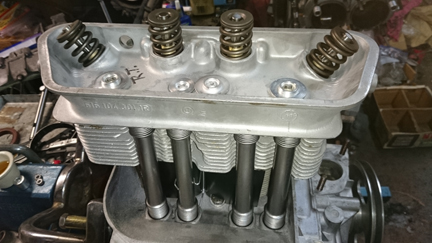
The heads have: New intake guides and several new valve seats, freshly ground valve seats, new valve springs, all freshly re-faced Original Porsche supplied valves. Plus, the heads have just been thoroughly cleaned, threads checked, etc, of course
I was doing cylinder head preparations for this engine along with its stable mate (found here) both at the same time, and thought I had taken photos of both pairs of heads. But, I was wrong; apparently I only took the photos of the other engine's heads as I was about to mount them. So when I went to mount these, I got them installed before reviewing photos and realizing I didn't have them.
BELOW, LEFT & RIGHT: The heads mounted, left and right, respectively. Note that the plating on the head bolts is mis-matched: some were done in a different batch than the others! For those familliar, the "small hats" (as Harry Pellow used to call them) are the shorter, later type that use a special washer, while the other six ("wide brimed") are the earlier longer type that don't take that special washer - they interchange fine so long as you put the washers in the right places!
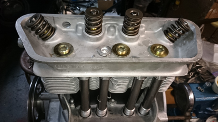
You can see in the many images that are here, the heads are pretty good - no broken fins, no cracks, new valve guides, good valve seats, etc. The only thing you don't get to see are the combustion chambers. They were as clean as its stable-mate (link above), but all four chambers had "conical cuts" because one cylinder had damage from some foreign object floating around in the chamber. The conical cut removes this damage by cutting it out and the result is a fresh, smooth surface. It's not perfect, but works well. The others are done this way, too, just so they match a little better. The depth of machining, however, were not matched (right head to left), and this is a good thing; don't take the metal out if you can avoid it.
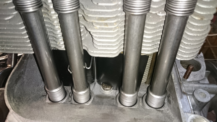
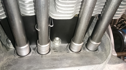
BELOW, RIGHT & LEFT: Here we can see the wire bails, through-bolt fastener, and acorn nuts are plated and the air deflectors clean and properly coated. In this instance, one of them is powdercoated while the other still has good original paint! Of course, new pushrod tubes are fitted to EVERY engine as a standard feature!
The next step was to consider which head should go on which side, and what any cylinder shimming should be. The shimming that was estimated at the start proved to be wrong, so shimming was adjusted. The compression ratio turned out to be 8.6:1, a small bit lower than the target of (not more than) 9:1 due to the conical cuts in the heads. But it's close enough, will make good power and it also provides a bit of safety considering the relatively poor quality of modern fuels.
Prepare the head "bolts" and washers, prepare the pushrod tubes, prepare the lower cylinder air deflection plates and their wire retainers, and get the torque wrenches set, and bolt on those heads!
Bolt up those rockers, adjust the valves - new jamb nuts, of course! - and pop on those valve covers!
Note that the rockers were hard-faced - there's a close-up image of them close to the top of this page. Also, there's an image of the pushrods, too.
BELOW: The rockers that went into this engine are one of the several sets below. These have all been thoroughly cleaned, hard-faced, and then re-cleaned. Hard-facing is required on old rockers now because the original surfacing hardening that Porsche applied has by now worn through. This restores the hardness and correct shape so the valve adjustment is stable and prevents a ledge from developing that makes setting correct adjustment difficult. A close up of the ends of a rocker can be found on this page near the top.
 For
good or ill, we somehow didn't take any photos as the assembly while it was
still on the engine stand, but picked up with the photography as we dismounted
it from the engine stand and set the crankshaft end-play during
For
good or ill, we somehow didn't take any photos as the assembly while it was
still on the engine stand, but picked up with the photography as we dismounted
it from the engine stand and set the crankshaft end-play during
AT RIGHT: The engine has just been dismounted from the engine stand and the crankshaft end-play was set while the engine was resting on this jack. The clutch is about to be installed, but you can see that it's a new 200mm flywheel with a VW depth clutch, though you'd have to really know your stuff to pick out that it has 12v starter ring gear teeth! You can, however, see that the fan looks new! It has been replated with cadmium.
As pointed out above, here are the choices we made in getting it ready for a VW application:
 356
/ VW mounting studs - These pieces help attach the engine to a transaxle
and are the lower pair of fasteners at the mounting flange. The 912 studs
are longer and cause installation headaches.
356
/ VW mounting studs - These pieces help attach the engine to a transaxle
and are the lower pair of fasteners at the mounting flange. The 912 studs
are longer and cause installation headaches.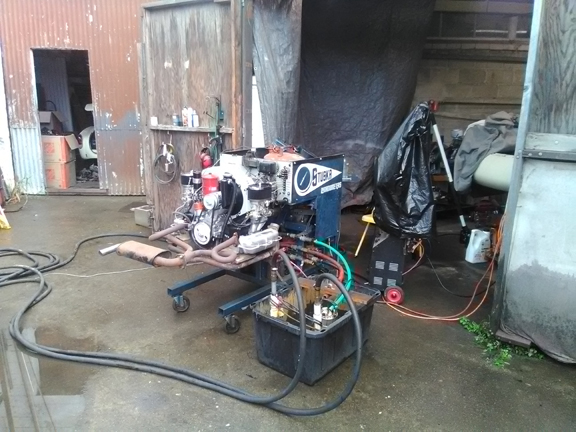
AT RIGHT: Dyno-day for this engine came on a rainy day! Thankfully, our Dynamometer is set up to be portable! We simply moved the running stand and control stand into the doorway of a large shed! The black hoses in the foreground are the water return hoses, the black hose running on the far side of the dyno is the supply line from the primary water pump, and the grey wire laying on the ground transiting from right to left and into the mass of hoses on the left is the interconnection between the dyno's control stand and the computer that controls the supply pump. On the right side of the dyno is a green hose - that's the vent. Then there's a red hose and that's the exit from the brake. Our Dyno can take two inputs and can have two outputs, but these secondary features are unnecessary when running-in engines and are only needed for very high horsepower output.
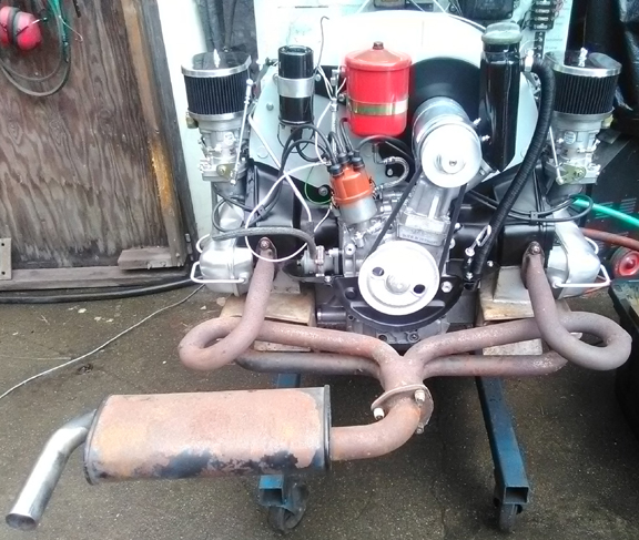
AT RIGHT: This engine, on the dyno - just a close-up from the image above. Note that it still has the new Webers on it, and not yet the spin-on full-flow oil adapter - see below for more on that.
At some point someone wanted to buy the engine configured to suit the buyer's needs.
Here are the steps we undertook to prepare it:
ABOVE RIGHT & LEFT: The timing cover was modified for the 356 application and shorter studs were installed in three of the top outboard positions. And, a small notch was cut in the left hand oil pump opening to accommodate the full-flow system's insert that prevents oil from skipping the filter and also provides for the return of oil (via the pump cover) from the filter). You can see that system's insert intalled in the right hand image.
 The
flywheel was swapped out for another with a 6V ring gear, still in 200mm and
still in the VW depth, and using a very particular pressure plate that has
a removable release plate so it can be used in a 356 which has either the
early clutch (with release plate installed) or the later version (for use
in transaxles with a guide tube for throw-out bearing, the release plate is
removed).
The
flywheel was swapped out for another with a 6V ring gear, still in 200mm and
still in the VW depth, and using a very particular pressure plate that has
a removable release plate so it can be used in a 356 which has either the
early clutch (with release plate installed) or the later version (for use
in transaxles with a guide tube for throw-out bearing, the release plate is
removed).
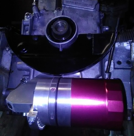
AT RIGHT: The full flow oiling system installed. Note the filter had to be trimmed. Why, and images describing the detail can be found here.
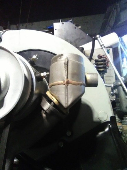 BELOW
RIGHT: Here, you can see the short breather canister not quite finished.
And the reason it's not finished is apparent: the right-most electrical
connector is in interference! There are various solutions to this!
BELOW
RIGHT: Here, you can see the short breather canister not quite finished.
And the reason it's not finished is apparent: the right-most electrical
connector is in interference! There are various solutions to this!
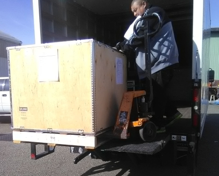
The engine was then crated and shipped to Dubai, part of the United Arab Emmerates. The customer alerted us late in the day on December 20 that they needed the engine in Dubai before January 1 to avoid a new import tax of some kind! I scheduled pickup for that Friday at 1PM, but unfortunately, the shipper called about four hours early - at about 9AM to say they had arrived for the pickup! Doah! ...So, the filler didn't get resolved, etc. Here's how it was when the time came to crate it:
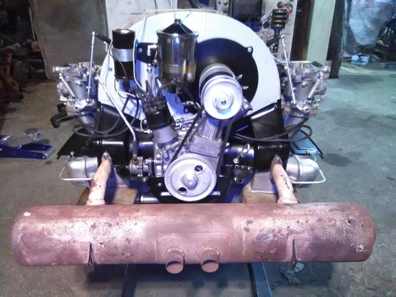
BELOW: The engine run with the newly rebuilt Solex 40P11-4s mounted specifically so they could be tuned. This required some serious doing because even though the customer had them done by a reputable shop, they float levels and injection quantities were way wrong and it took a fat half-day to rectify ... which contributed to not being fully ready the day before the shipment pick-up. (The muffler was a loaner. Note that it isn't that great anyway; pinholes.)
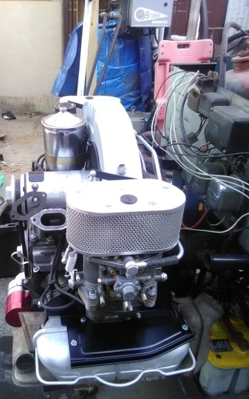
BELOW, RIGHT & LEFT: The engine as it was when the time to crate came...
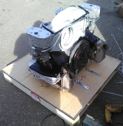
BELOW, RIGHT & LEFT: Here it is on the pallet that makes up the bottom of the box, attached to the crate. No time to clear things for a more pretty image, the trucker was already there pacing back and forth!

Finally, the crate sides and lid go on, some packing for the small bits and out it went:
Because some people are keeping logs of VIN and engine numbers and then purport to tell people what someone else has, out of respect and concern for a buyer's privacy, exact VIN and engine number data are not published here.