Copyright © 2007 - 2024, Coachworks For contact data Click Here.
Copyright © 2007 - 2024
Copyright © 2007 - 2024,
Coachworks For contact data
Click Here.
![]() has been retained for reference purposes.
has been retained for reference purposes.
 Porsche
Engine for Sale:
Porsche
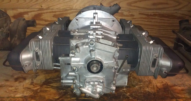
Engine for Sale:This engine, in long-block form, is ready for pickup or delivery today, and may be purchased complete, ready to install, with only a few days delay.
SPECIAL NOTE
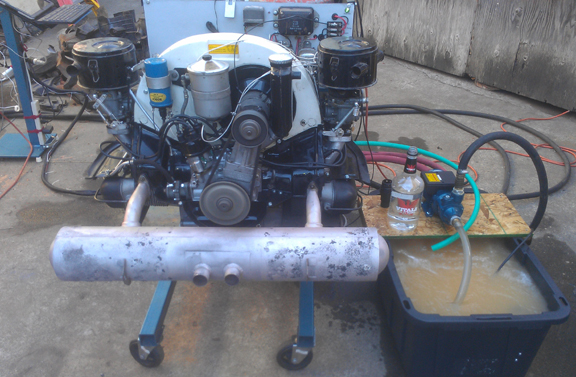
This engine has been "run-in" as per Porsche factory specifications as outlined in the Workshop Manual, operations 52 EN, 53 EN, and 54 EN, pages E83 and E84. This engine, undergoing the run-in process, can be seen below.
 AT
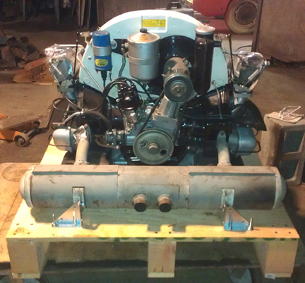
RIGHT: The engine being run-in on our Stuska water
brake engine dynamometer. This image was taken just as the run-in process
was near its end, with the engine running at 3500 RPM, with a load of 44 ft
lbs. Note that the smaller return pump employed here is fine for lower loads
earlier in the run-in process but can barely keep up with this pace. A larger
return pump is used for higher loading. ...No, that's not vodka! - that's water
used to prime the pump shown. Note that the buyer of this engine provided a
"core" from which the parts visible in this image to make a complete
engine were obtained.
AT
RIGHT: The engine being run-in on our Stuska water
brake engine dynamometer. This image was taken just as the run-in process
was near its end, with the engine running at 3500 RPM, with a load of 44 ft
lbs. Note that the smaller return pump employed here is fine for lower loads
earlier in the run-in process but can barely keep up with this pace. A larger
return pump is used for higher loading. ...No, that's not vodka! - that's water
used to prime the pump shown. Note that the buyer of this engine provided a
"core" from which the parts visible in this image to make a complete
engine were obtained.
This 1964 356 C engine is "numbers matching" with factory Big-Bore pistons and cylinders, and has just undergone a complete overhaul, and is fully balanced for smooth running, long life, and a few more HP.
The engine is a C so it is effectively the best combination of durability and performance of any 356 engine ever made. One can think of the C as a slightly de-tuned SC. It has all the best engineering ever built into a 356 pushrod engine. So, of course it has the late-type oil pump, late rockers, etc. During this rebuild it was fitted with OE Big-Bore pistons and cylinders, and it has a few components from less than a year's earlier production, 1600S, as outlined below.
Every detail about the engine has been attended to, as outlined below; nothing was ignored.
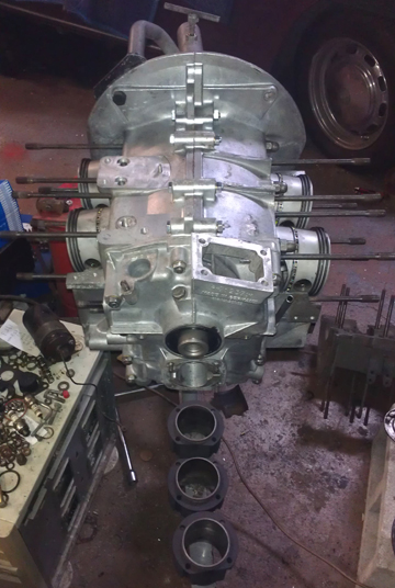
Here it is as a long-block, ready for pickup or delivery (above).
I received this engine as a core from the sale of this SC engine to Scott Wilson. He accepted delivery of the SC and gave me this C during a trip I made to Mojave in an attempt retain my land-speed record in the 36hp Challenge. (Unfortunately, while on my first run, I achieved a new record speed at 119, but over-revved the engine, a piston struck a valve, and I limped across the finish line at a modest 90.5.) I happened to be too caught up in my racing to have taken images of the engine as we made the exchange.
Scott ran this engine for a while, maybe 10k miles, and then it started to make a noise and he decided to get a rebuilt engine, since this one was not original to his car anyway. The history of the engine beyond that is not known to me, but Scott indicated that it had been "recently rebuilt" right before he put his ten thousand miles on it or so. I found it to be a typical (bad) rebuild. There were loose fasteners, some that were way too tight, and lots of "small" installation errors.
 Scott
tore this engine down to effect shipping to me, so when I got it, it was just
a few boxes of parts.
Scott
tore this engine down to effect shipping to me, so when I got it, it was just
a few boxes of parts.
Among the various parts, some of which are fine and some of which I elected not to use.
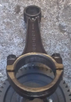
One example of something I elected not to re-use are the connecting rods. Not only was one of them damaged in the pin area from past trauma, the following image you can see that these rods were machined improperly by someone.
Note the oil hole at the base of the small end of the rod. Such oil holes are firstly completely unnecessary, and secondly, they are a frequent cause of catastrophic failure in high-performance engines. I prefer not to ever use rods that have had this done to them, or only use them in very low-stress applications.
I also elected not to re-use the camshaft gear (on the cam), and various other bits.
Since I don't have images to show here anyway (other than the rejected rod at right), we'll just move on - you can see what is used in this engine rather than worrying about what isn't!
 Crankcase
Preparation
Crankcase
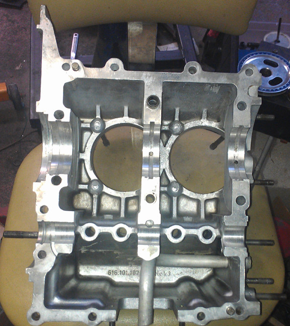
Preparation Visual inspection revealed that it needed an "align-bore" - re-boring the crankshaft bearing bore to the next larger size. To confirm this, torque it up, measure the bearing bores, and sure enough, it needed it. Otherwise, the case suffered a few dings inside, but was overall OK. I took a "die grinder" to the worst of the dings - not so bad really, and just smoothed things out. We don't need stress risers!
I then measured the cylinder spigots (on each side) to ensure they're all in the same plane with their neighbor (and not angled or of differing height) - they're perfect. And then I checked carefully for any cracks, damaged threads, etc. These checks revealed no flaws.
The next step was to perform the align-bore and then thoroughly clean the case.
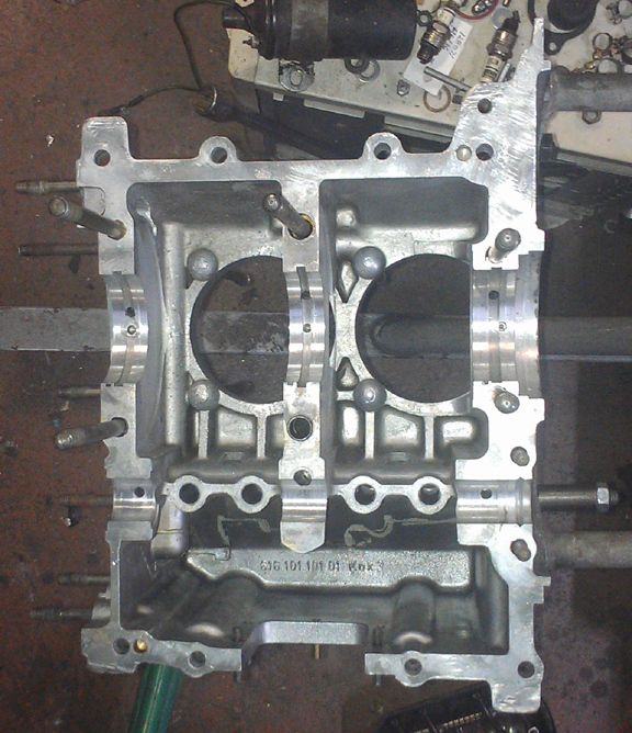
At right we see the left case half after it was align-bored and cleaned. The image doesn't do it justice - it's very clean; the slightly dark speckles that can be seen in some places are merely artifacts of the fact that the metal isn't perfectly smooth in some places. The surface at the joining plane with its other half is very close to perfect.
After the photo at right was taken, I paid a lot of attention to the oil sump studs, setting their height correctly so they can once again be fitted with cap nuts. Cap nuts help ensure that the studs are not damaged by dragging the engine on the pavement or from errant road debris, etc, as such damage will prevent the nuts from coming off and thus will necessiate the removal of the studs. This is bad. The studs should stay in the case as much as possible!
Two studs needed outright replacement and all needed height adjustment. They're fine now. And while at it, I also replaced the missing M6 oil cooler stud.
Now, the other side.
 The
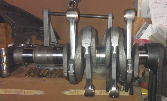
crankshaft is a proper "C" type, and it's in beautiful condition.
It was magnafluxed to check for cracks, then re-ground on both rods and mains
to first undersize, and thouroughly cleaned and polished.
The
crankshaft is a proper "C" type, and it's in beautiful condition.
It was magnafluxed to check for cracks, then re-ground on both rods and mains
to first undersize, and thouroughly cleaned and polished.
The original rods were flawed - as described above in the teardown section - so I replaced them with another late-type set. Of course, they're fully rebuilt! I rebuild rods in batches - it's easier / faster / cheaper that way as it keeps setup time to a minimum. The rods used are one of these sets at right - I'm not sure which set, as they're all late rods, all balanced to 0.1g, etc, rebuilt as described below.
 For
me, "rebuilding the rods" means to:
For
me, "rebuilding the rods" means to:
This is all standard work so there aren't any photos of them in-process.
 As
usual, I mounted the crankshaft up on the ole crankshaft stand and mounted up
the rods, as you can see above right.
As
usual, I mounted the crankshaft up on the ole crankshaft stand and mounted up
the rods, as you can see above right.
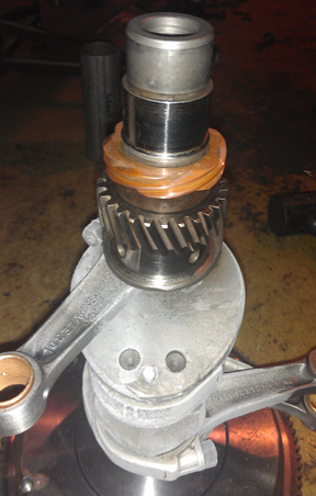
Afterward, I installed the crank gears as per my usual technique - I don't press them on and risk damaging the crankshaft (straightness!), and instead use temperature differential; they go thunk! into place. However, just as I was about to install the gears, I realized there was no woodruf key in the gear section of the crank! So, reaching into my bin of new woodruf keys, I installed a new one. (The circlip went on after this image was taken.)
The order of assembly of the crankshaft isn't too vital. There's setting the end play with the flywheel and bearing, there's mounting of gears, and there's mounting of the rods. In this instance, I happened to leave the flywheel for last because there was some question as to which flywheel I'd use. I decided to forge ahead with this new reproduction flywheel that has had a little bit of service but is still in great condition, and a likewise slightly used but great condition pressure plate, balanced together...
It's a 200mm version, 6v, and is somewhat lighter than stock.
I then went to mount it up and discovered that something happened to all the dowel pins! I had somehow overlooked this, but they were all gone! The holes were perfect, though. I really don't recall just what happened to the woodruf keys and dowel pins, but, well, that's what people like me keep new stock around for!
So, I broke out the ole tub of new, hardened flywheel dowel pins and installed a set. Here's a photo of installing the new dowel pins - pretty aren't they? (The correct ones are hard to find.)
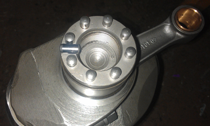
Yes, there's an extra one sitting on the surface, just so you can see what they're like. One end is tapered a bit and this helps install them. These things are damned hard. They fit into their holes very tightly. I was careful to set their hight specifically, so they fill the flywheel depth but just barely do not stand proud of the surface where the gland nut goes.
That done, it was then time to set the crankshaft end play. I forgot to take a photo of it, but you basically install everything the way it would be in-situ, except not in the actual crankcase, and torque it up. You then measure with a feeler gauge the gap and swap out shims until you get it right. Then, a new iron gasket is used for final assembly later, after the case halves are assembled.
Oh, and here's that flywheel and pressure plate:
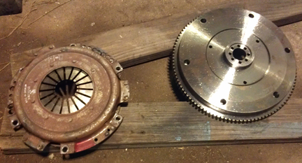
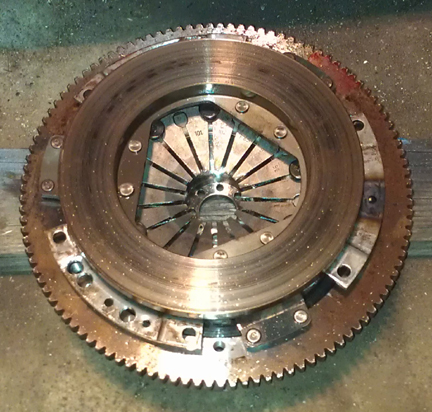
Note the fingers of the diaphram of the clutch - these are the tell-tale signs of the youth of this clutch plate - that, and the good condition of the friction surface. The flywheel is similarly like new. ...These imags were taken when it was dark, and most were too blurry to use, but the darkness also made the slight surface rust look worse than it is. I thoughtfully coated them in WD40 to prevent any further corrosion in the short term.
(Sorry I got the image sizes different!)
I had bought these new and they do have some service life on my "spare" engine, which I have decided to rebuild. They only have about 2 thousand miles on them or thereabouts - its in the log book! What surprised me is how usually I have to struggle to get a new flywheel onto new dowel pins yet this time the flywheel went on easily, about the same as a flywheel (and dowel pins) that's been installed and removed a few times more than just twice as this one has. I think the reproductionists must have had complaints and loosened up the fit a tiny bit.
 Camshaft
and Lifters
Camshaft
and LiftersThe original camshaft, a genuine "C", appeared to be in great condidtion, so I decided it should be re-used, but as I cleaned it for use, I discovered it wasn't so good after all. So, time to select another.
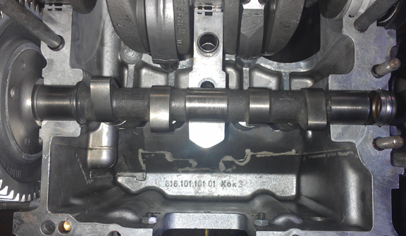
I selected an "S" from less than a year earlier - the first half of '63. (You can see it in the image at right.) It's a fine cam, in great condition, not a regrind. Not only are the lobes good, but so is the oil pump drive slot, where, by the way, you'll find the "16" that denotes it as a "Super" cam. (You'll see the end of the cam in images taken when the halves are bolted together.)
Meanwhile, the original lifters looked fine, but they had to be refaced. If you're going to re-use them, they should go back in the exact spot they were in before, but when you change the cam, you must reface the lifters. So, reface... The lifters are a late ATE version, and there are no known problems with them, unlike some of the earlier iron ones that sometimes lose their heads!
You can see the lifters as the case halves go together (below) - though you can see the edges of them in this image (above)!
 Crankcase
Assembly
Crankcase
AssemblyOne of the first things one does is check the bearing fit, and on a freshly align-bored crankcase, that went quickly. The new bearings are not the modern ones Stoddard sells today, which are a heavy type with little crush. No, these are much lighter and the full-circle bearings are a little larger in diameter for the original amount of "crush" to hold them tight in the case - they're old-school "Repco" brand, one of the tried and true aftermarket parts makers of old, long since out of production.
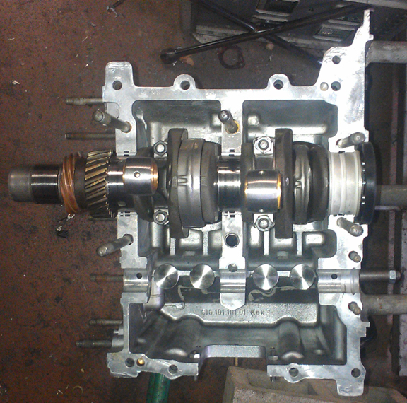
Next, one sets the crank in place, pushes the thrust bearing home on it's dowel pin, and checks the fit of the camshaft. I used a new dowel pin in the flywheel main bearing too, by the way (bearing 1).
In the image at right, notice the main bearings: The two "middle mains" (bearings 2 and 3) are each "halves". This is characteristic of C era crankshafts and their bearings as the middle mains are both 55mm in diameter (nominally), while on the earlier B cranks, the journals are 50mm. So these bearings are bronze or steel backed as they are about half the thickness of the B bearings they supercede. If bearing three is a full-circle bearing (you have to take the gears off to access it), then it's a B crankshaft! This is definetly a genuine C as confirmed in these images.
Also worth pointing out here - as described in the cam section above - that I refaced the cam followers. You can see the refaced lifters at right - the opposing pizza-slice shaped reflections give them away.
The cam was trial fit, and, I actually had to de-select the first one chosen (the original C from the core I received), but as described in the camshaft section above, it was flawed. So the image in that section shows the actual trial-fit to match up the cam gear.
 I
take special care with cam gears. One thing I always do that not many other
engine builders take the time for is polishing the teeth of the drive gear that's
mounted to the cam. I do this because firstly there's usually a bit more dirt
in between the teeth than most people realize, and taking time with every tooth
helps guarantee they're clean. Secondly, a coating of oxidation can make the
gear appear to be bigger than it really is, and when the oxidation wears off
(fairly quickly - contaminating the oil, by the way), the gear becomes a bit
looser. Unfortunately, I didn't realize my photos didn't show very much of the
polished gear until after the halves were together! Oh well, you can look at
other engines I've built and see what I mean - I nearly always do this unless
the gear was just in service.
I
take special care with cam gears. One thing I always do that not many other
engine builders take the time for is polishing the teeth of the drive gear that's
mounted to the cam. I do this because firstly there's usually a bit more dirt
in between the teeth than most people realize, and taking time with every tooth
helps guarantee they're clean. Secondly, a coating of oxidation can make the
gear appear to be bigger than it really is, and when the oxidation wears off
(fairly quickly - contaminating the oil, by the way), the gear becomes a bit
looser. Unfortunately, I didn't realize my photos didn't show very much of the
polished gear until after the halves were together! Oh well, you can look at
other engines I've built and see what I mean - I nearly always do this unless
the gear was just in service.
Now, time to put the case halves together! Prep-work done correctly, this goes easily and quickly. Apply sealant and bolt it up!
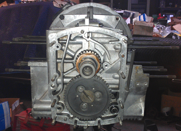
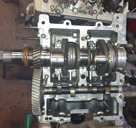
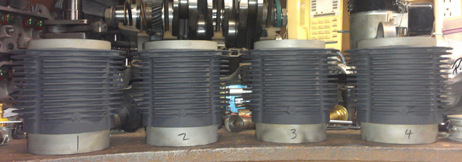
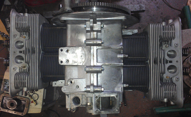
That goes rather quickly, the timing cover goes on, and here we have it as a "bottom end," also known as a "short block."
 Cylinder
Heads
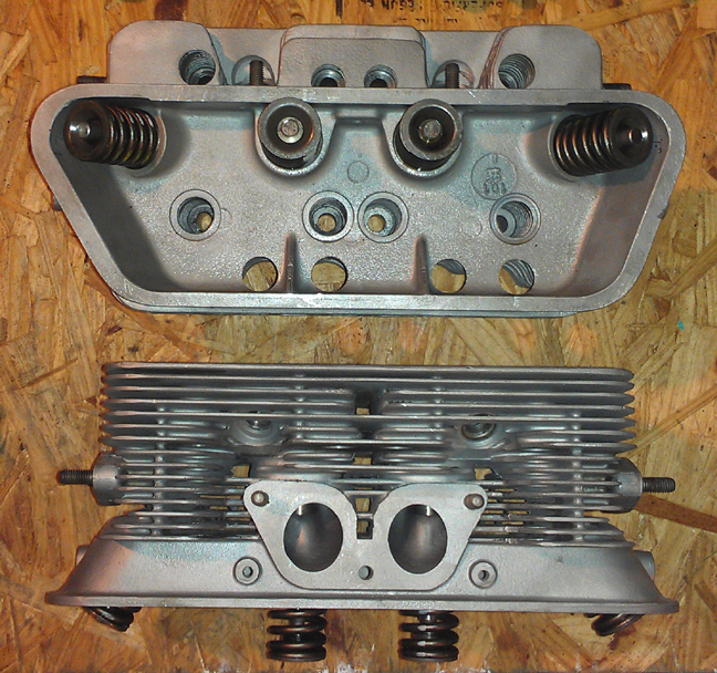
Cylinder
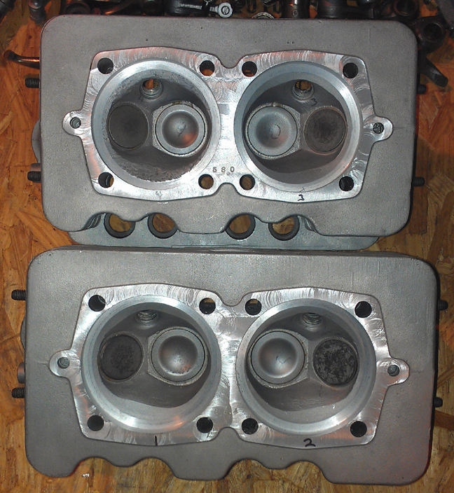
HeadsThese heads are in very good condition and were mated as an original pair from new. Here's a summary of their features:
Perhaps I should have flip-flopped the order here and put the pistons and cylinders section before a discussion of the heads because the choice of these heads was mated with the choice of pistons and cylinders for a very well rounded setup that will produce a bit more HP than a stock C engine.
Keep reading and it will become more clear.
The heads are actually from the very last of the B series in the summer of '63, just immediately prior to the C, and will actually out-perform the original C head in this application. In the summer of '63, Porsche decided to save on production costs by making only one cylinder head casting for each of its two pushrod engine offerings, so, of course, they went with what the higher performance SC needed. However, to offer a lower-cost, lower-HP version, they merely bell-shaped the bottoms of the intake manifolds to the previous design (Zeniths), and the result was a bit of a mis-match; the air flowing through the manifold tends to lose some velocity right as the manifold joins the larger ports in the head. This is a well-known design oops that they apparently did on purpose because it just doesn't matter that much since the carburetion sitting on top of it was restricted anyway.
 However,
in this instance, by fitting the last B head with the Zenith manifolds, we're
fixing that oops! And in combination with the factory big-bore pistons and cylinders,
the engine will have more displacement, so, more power. In fact, these two,
this pair of heads and these pistons and cylinders, make a wonderful pairing,
yielding a healthy compression ratio that will still be safe with inexpensive
(lower octane) gasoline without the need to substantially shim the cylinder
bases (as is needed with other big-bore sets), so everything still fits properly,
while adding about 9% to the displacement.
However,
in this instance, by fitting the last B head with the Zenith manifolds, we're
fixing that oops! And in combination with the factory big-bore pistons and cylinders,
the engine will have more displacement, so, more power. In fact, these two,
this pair of heads and these pistons and cylinders, make a wonderful pairing,
yielding a healthy compression ratio that will still be safe with inexpensive
(lower octane) gasoline without the need to substantially shim the cylinder
bases (as is needed with other big-bore sets), so everything still fits properly,
while adding about 9% to the displacement.
Additionally, these heads are stronger as C, and SC (and 912) heads are prone to cracking between the spark plug bore, intake seat bore, or exhaust seat bore - or any combination thereof - when overheated.
Some mention of the more typical commentary about heads may be helpful. Firstly, these heads have had their valve guides replaced with modern silicon-bronze type which are long-lasting and are easy on the valves.
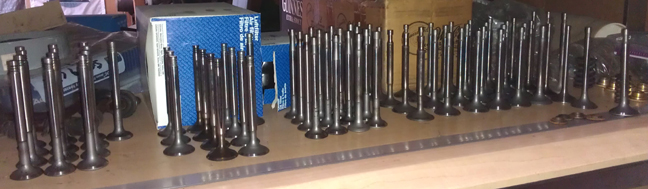
Fitted to these are great valves. They're originals, not aftermarket replacement which are all you can get new today. Of course, the valves have been checked for length (stretching makes them unworthy), polished, and refaced, so they're effectively perfect.
New springs, of course, carefully selected. Previously, we went through a large batch of about 40 new springs and they were grouped by strength. We match up slightly stiffer springs with the heavier valves (intakes are about 2% heavier than exhausts), so they're very close sets, matched up, so all the valves tend to float at the same time. ...Of course, each valve and retainer are position-specific through the shimming process...
The valves were selected from the cache of valves shown here, all re-faced and with stems polished (below right).
 After
the valves are fitted, the combustion chambers are measured with a burrette.
The results go into a process of matching up with the "CAC" data collected
earlier (and described below). This helps guide the decision on which head goes
on which side, what, if any, shimming will be used, and what additional remedial
action might be taken to improve the matching of the cylinders to each other;
the more similar the net HP produced among all cylinders helps improve overall
engine output, engine tractability, and longevity.
After
the valves are fitted, the combustion chambers are measured with a burrette.
The results go into a process of matching up with the "CAC" data collected
earlier (and described below). This helps guide the decision on which head goes
on which side, what, if any, shimming will be used, and what additional remedial
action might be taken to improve the matching of the cylinders to each other;
the more similar the net HP produced among all cylinders helps improve overall
engine output, engine tractability, and longevity.
 Pistons
and Cylinders
Pistons
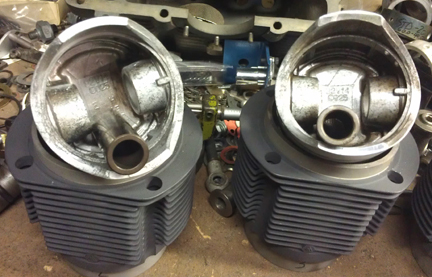
and CylindersGiven the old adage, "there's no replacement for displacement" - and there isn't! - this great set of Porsche Big-Bores is being fitted. Unlike most "big bore kits", these are 85mm (as opposed to 86), but they don't have a large crown that goes into the combustion chamber. The result is significantly increased displacement without requiring high-octane, and without having to space out the cylinders to achieve a reasonable compression ratio (which also means it's not changing the width of the engine, and the attendant issues that come with that, like how well the cooling tin fits, the lengths of the pushrods, and so forth).
These are Mahle pistons fitted to Porsche-labled cylinders.
 We
always check the match of pistons to cylinders and match piston weights
as a set, and provide any remedial action to correct any errors before installation.
For example, by shuffling around the piston pins among the pistons, one can
usually improve the matching of piston weights. This set naturally balanced
(without removing material) to within about 2.8 grams - the official specification
is ten grams (10g) - however, I switched around the connecting rod pins and
got it to within about 0.8g, then trimmed one piston to bring them into virtual
perfection.
We
always check the match of pistons to cylinders and match piston weights
as a set, and provide any remedial action to correct any errors before installation.
For example, by shuffling around the piston pins among the pistons, one can
usually improve the matching of piston weights. This set naturally balanced
(without removing material) to within about 2.8 grams - the official specification
is ten grams (10g) - however, I switched around the connecting rod pins and
got it to within about 0.8g, then trimmed one piston to bring them into virtual
perfection.
The cylinders were:
The pistons were:
So, now the pistons and cylinders are ready.
For many shops, from this point, installation goes very quickly, but we think this is where one needs to take one's time! The key reason one needs to take time here is that there are production tolerances on every part in an engine, and while a set of parts may look identical, there's often subtle variation between members of a set, and there are sometimes significant errors in production that weren't caught by the manufacturer's quality control processes. These errors can "stack up" and cause problems if not discovered and corrected.
 Here's
our process: Two of these steps require special tools most shops don't
have.
Here's
our process: Two of these steps require special tools most shops don't
have.
We like to carefully measure everything and then mix-and-match the parts for superior fit. We have also discovered significant manufacturing errors with this process which would likely have gone unnoticed without these measures. It is remarkably easy, for example, to overlook the circumstance of the crankshaft bore not in the true center of the crankcase, angled on the horizontal left or right of center, or not on the same horizontal plane at all. Yet examples of errors like these are not as uncommon as we would like.
Here you can see two cylinders being fitted for height comparison check - this is done to ensure that there are no difference between the cylinder heights that the head itself "sees." The book value for tolerated error is 0.1mm (four thousandths of an inch), but in this case, there was no measurable differences.
OOPS! The height comparison check image(s) is(are) missing! I'll fix that shortly!
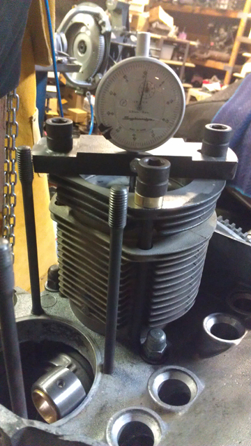
The next thing we do is something nobody else does (that we know of) in the engine building process, and that is to measure the height the piston crown comes above the plane of the top of the cylinder. I call this the CAC, or "Crown Above Cylinder." This value is important because, firstly, it can reveal deeper problems, and because it helps us get the compression ratio equal in all four cylinders.
Here are some of the deeper problems that can be discovered through a CAC check:
 An
improperly ground crankshaft
An
improperly ground crankshaftIn order to do this for these engines, you have to have special tools. Here, you can see them in action on this engine in the images above.
Even if you can't read the needle in the CAC measurement image, the distance between the smallest tick marks is one hundredth of a mm, or 0.0004" - that's less than half a thousandth of an inch! - and you can discern to perhaps a tenth of that! So, this is a very accurate measure, performed while the cylinder is under torque, so any shims are squished flat, etc.
The accuracy is so good, that if you take the time to swap parts around, you can accurately determine discrepancies in the manufacture of the various parts! Yes, we ARE splitting hairs here! However, a benefit to both engine builder and customer is that the ability to move parts around for better fit means that perfection is more easily achieved, and the more equal the HP production of each cylinder, the smoother the engine will run, and the more HP the engine will produce overall.
Because this process includes the entire assembly, torqued as in service, and measures the height each piston protrudes out of its cylinder, all errors in connecting rod lengths, cylinder heights, crankcase spigots depths (cylinder bore deck), piston connecting pin heights, and shim thickness' are accounted for in the measurement results. There is no superior method.
After all of that, the rings were fitted per cylinder and end-gaps checked. Then the rings mounted, pistons mounted, and then the cylinders.
 At
this point the engine is ready for its cylinder heads, and this work went very
quickly - as it should! - as all the prep work was already done.
At
this point the engine is ready for its cylinder heads, and this work went very
quickly - as it should! - as all the prep work was already done.
I media blasted and then re-painted the lower cylinder air deflector plates with barbecue black high-temp paint.
Prepare the head "bolts" and washers, prepare the pushrod tubes, prepare the lower cylinder air deflection plates and their wire retainers, and get the torque wrenches set, and bolt on those heads!
My pattern is to mount one head, torque it to 7 ft lbs (as per the manual), then mount the other head the same way, and then alternate between the heads with an ever-increasing torque up to the final torque value, then repeat the final value until the fasteners no longer turn when torque is applied.
 OK,
mount the valve gear, adjust the valves and pop on the valve covers - sounds
simple and quick!
OK,
mount the valve gear, adjust the valves and pop on the valve covers - sounds
simple and quick!
And, it should be, especially since the rocker's contact faces on the valve stems were previously refaced and showed little wear. (See image at right.)
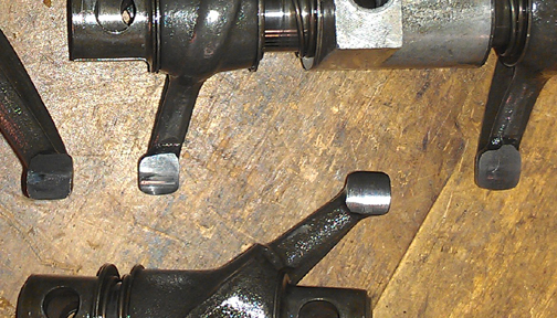
However, Not So Fast! When I bolted them up and set about adjusting the valves, I noticed that many of them, especially the exhausts, only contacted the valve stems on one tiny spot! (See image below.) That's not right! This condition will quickly create a step which makes it is increasingly difficult to get a proper adjustment.
Investigation showed that indeed, the rockers were refaced incorrectly! They are supposed to be refaced so that the curve on the contact face is parallel with the rocker's shaft. These were not!
&*&%*&%!
Note in the image below how the rocker contacts only at the extreme left edge of the valve stem.
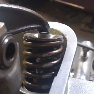
(Also note in the image above how the valve cover gasket sealing surface becomes narrower as it approaches the exhaust valve spring - this is a characteristic only seen on very late heads.)
 So
much for "competent machine work" these days! Well, I give them credit
for knowing they had to do something, but maybe going to someone competent would
have been a better choice? One would think.
So
much for "competent machine work" these days! Well, I give them credit
for knowing they had to do something, but maybe going to someone competent would
have been a better choice? One would think.
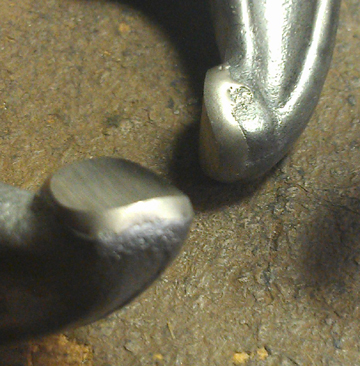
So, I had to re-reface them. But of course, that's not enough, either, because to correct the large angle on the faces, a lot of material had to be machined off - not just a simple skimming as is usually required - and because these parts are only surface hardened on the contact face, resurfacing the contact face penetrates through the hardened surface in to the un-hardened material beneath.
The correct solution therefore - and the one employed here - is to weld on material called "hard face", then reface again to provide a smooth surface with the right arc, on axis with the rocker's shaft. (See image at right.) "Hard facing" is effectively a very hard steel. This new material not only provides a hard surface, but the process can make up for the loss of material from this refacing plus all the previous refacing work this set has received over the years.
Ah, well, that's how it goes sometimes.
Oh yes, I should mention that along the way, the rockers were media blasted, blown out with compressed air, and new adjustment nuts were fitted, of course!
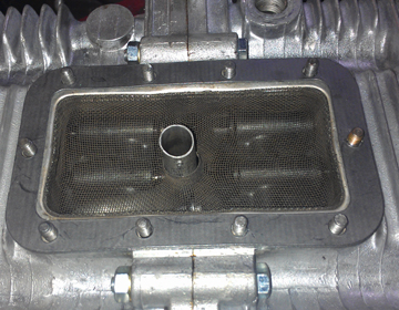 Then
fit the oil drain plug, and sump screen and plate. I used new cap-nuts to protect
the studs into the future. (Recall, as noted above, that the oil sump studs
were previously attended to - height-adjusted / replaced as needed.)
Then
fit the oil drain plug, and sump screen and plate. I used new cap-nuts to protect
the studs into the future. (Recall, as noted above, that the oil sump studs
were previously attended to - height-adjusted / replaced as needed.)
Then, fit the two oil control pistons. I used new springs because I figured the old ones had been compressed for some 40 years!
Can't forget the oil pump! In the images below, the cover for it is still in the parts washer - it should be gleaming just as much as the rest of the engine!
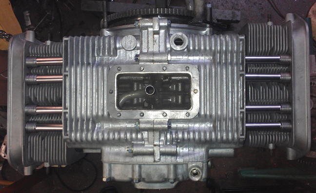
Here, missing only the oil pump and valve rocker assemblies:
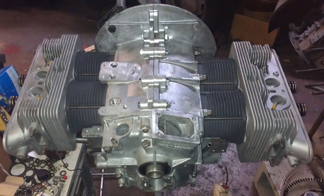
And now here it is (below) as the longblock, ready for pickup or delivery. Note that the valve covers are the non-vented type (correct for C), and have been media blasted clean and painted (only on the outside) in the same high-temp paint as the cylinders - barbecue black.
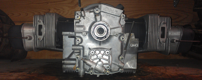
For the ultra-sharp eyed, yes, sticking up behind this engine is the just visible cast-in "generator stand" of a two-piece case Porsche engine type 546. It is presently available, too. It's description is here.
After this engine was completed, the buyer opted that it be "run-in" as per Porsche factory specifications as outlined in the Workshop Manual, operations 52 EN, 53 EN, and 54 EN, pages E83 and E84. The buyer provided a "core" to complete the engine with - fuel pump, carburetors and so forth. The running-in of the engine on the dynamometer can be seen in the second image from the top of this page.
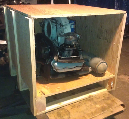
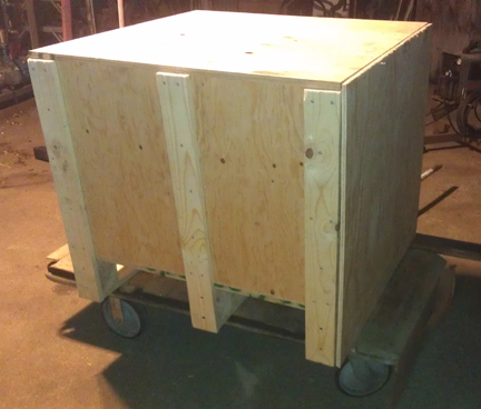
Subsequently, a crate was made...
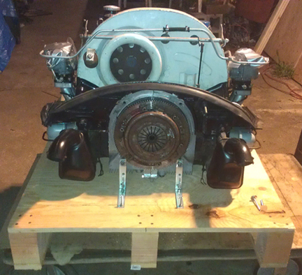
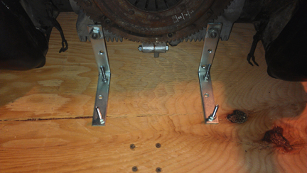
The bolting down of the engine to the custom-made pallet is a bit trick, isn't it?! Here are some close-ups:
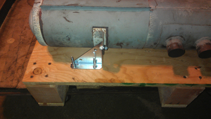
BY THE WAY, No, those heater control arms are NOT touching the pallet - they were damaged by the fools who crated the core engine when they shipped it here. They had stuffed wooden blocks around the engine in lieu of actually tying it down to the pallet (different crate). I didn't straighten these parts because that's properly the job of the guy who damaged them in the first place - who happens to be the fellow (not the buyer) who's going to install this engine upon arrival!
Also note that to do this right, you must use special bolts to come up from underneath - we dont' want anything to hang up on forklift tines! They WILL destroy a crate, and you could lose an engine if a forklift rams bolts hanging through OR comes up and pushes a bolt through! So, don't use anything that sticks down into harm's way. Instead, use these:
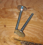
The huge head won't pull through and when you tighten them up with a large flat surface on the top side too, they actually make the plywood stronger!
Yes, you knew this was coming:

Because some people are keeping logs of VIN and engine numbers and then purport to tell people what someone else has, out of respect and concern for a buyer's privacy, exact VIN and engine number data are not published here.