Copyright © 2007 - 2024, Coachworks For contact data Click Here.
Copyright © 2007 - 2024
Copyright © 2007 - 2024,
Coachworks For contact data
Click Here.
![]()
 Porsche
Engine
Porsche
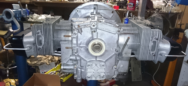
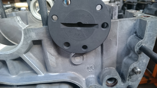
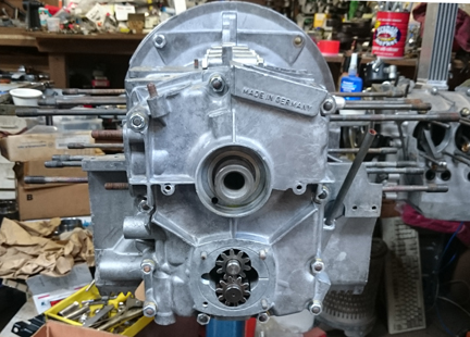
EngineAT RIGHT:Almost ready - the oil pump was still in the parts washer when this image was taken!
This engine has been prepared in long-block form, but may be purchased complete, ready to install, with only a few days delay.
 This
engine is optionally available Run-In on our Stuska water-brake
engine dynamometer as per Porsche factory specifications as outlined in
the Workshop Manual, operations 52 EN, 53 EN, and 54 EN, pages E83 and E84.
You can see this being performed on another of our engines here
- see the second image down.
This
engine is optionally available Run-In on our Stuska water-brake
engine dynamometer as per Porsche factory specifications as outlined in
the Workshop Manual, operations 52 EN, 53 EN, and 54 EN, pages E83 and E84.
You can see this being performed on another of our engines here
- see the second image down.
This 356 SC engine has just undergone a complete overhaul, and is fully balanced for smooth running, long life, and a few more HP.
 This
engine has all the equipment that Porsche itself would have provided as an SC
replacement engine under the KD program during the era in which the crankcase
was constructed, with the exception of big-bore pistons and cylinders and a
new camshaft with identical timing but a tiny bit more lift. The cylinders are,
however, "biral" (aluminum fins over an iron liner), just as the originals
were. For longevity, this engine also has nikacil lined cylinders.
This
engine has all the equipment that Porsche itself would have provided as an SC
replacement engine under the KD program during the era in which the crankcase
was constructed, with the exception of big-bore pistons and cylinders and a
new camshaft with identical timing but a tiny bit more lift. The cylinders are,
however, "biral" (aluminum fins over an iron liner), just as the originals
were. For longevity, this engine also has nikacil lined cylinders.
This engine has no type numbers or "casting number" stamped into the main half pairs, and no serial number stamped into the timing cover. The only numbers stamped in the case are the "match numbers" used to ensure that parts which were machined together remain together. The month of casting was cast into the case halves are March, 1969. This was near the end of the 912 era, so it has all the best improvements, and Porsche machined the timing cover for service in 356 automobiles, as was done for all 356 replacement cases after 356 production ended in 1965.
During this rebuild every detail has been attended to; nothing was ignored.
This engine came to us from a customer who bought a similar engine from us. He was an original 356 SC owner and this engine was a replacement he obtained in 1969 when his original engine had a melt-down while driving through the desert on his way to active-duty military service. From the description of what happened, the shop that did the work ripped him off. But that's another story. We received this as a complete engine, stripped it to a long-block and installed the removed parts on the engine he bought from us. And, he wanted to sell us his core for credit against the engine he was buying, so we tore it down immediately.
 Crankcase
Preparation
Crankcase
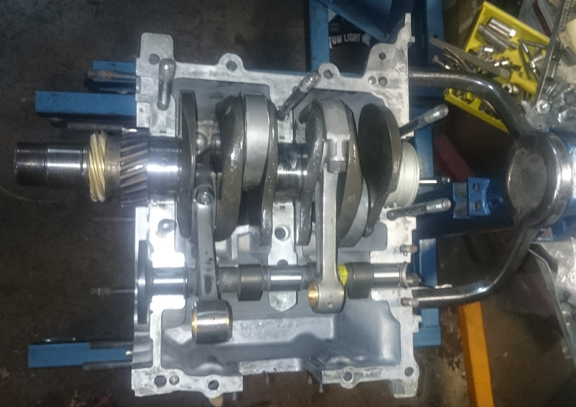
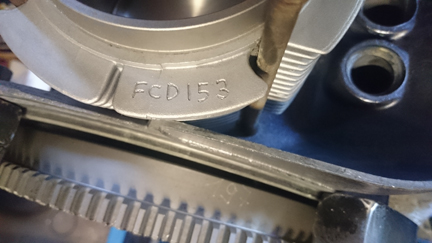
Preparation This crankcase cleaned up nicely and didn't need any special preparation before reassembly. The case was previously align-bored to first oversize and is virtually perfect. We were so happy with it, we immediately started some form of assembly, even before thinking to take our usual photos of the case halves open and bare, though there are some here that show the insides pretty well. This image shows both the cam we installed - it's a new one from Dima Elgin - has a bit more lift but is otherwise stock, and the bearings being trial-fit.
AT RIGHT: The left case half with the main bearings and camshaft being trial fit. Note the casting date below and to the right of cam-center. The dots inside the circle indicate month, so this one is March, 1969.
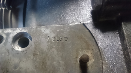
As the case was align-bored, it's customary to mark the case, so, since the former person didn't, I did, as seen here:
BELOW LEFT: The crankcase's new crankshaft bore, marked in mm.
 The crankshaft
is a genuine "SC / 912" crank and was checked for cracks and rotationally
balanced on its own. Actually, it's fairly late in production - during the 912
era, like the case. The guy who did the magnaflux (checking for cracks) spritzed
it with WD40 to keep it from rusting - you can see some remains of it on the
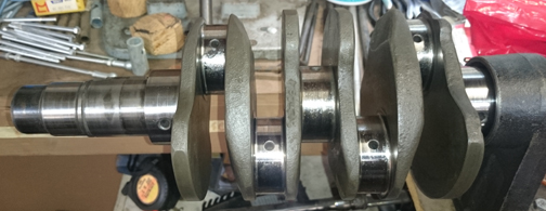
journals. ... It's "standard, 1st under".
The crankshaft
is a genuine "SC / 912" crank and was checked for cracks and rotationally
balanced on its own. Actually, it's fairly late in production - during the 912
era, like the case. The guy who did the magnaflux (checking for cracks) spritzed
it with WD40 to keep it from rusting - you can see some remains of it on the
journals. ... It's "standard, 1st under".
AT RIGHT: The crankshaft used in this engine - late 912 production. It's been spritzed with WD-40 to keep it from rusting until installed...
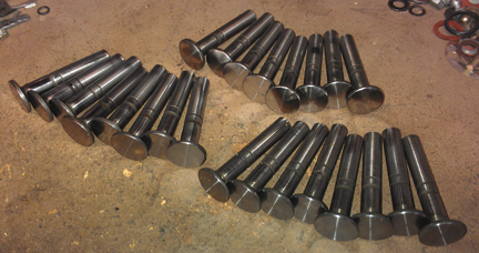
As usual, I rebuilt the connecting rods. I did not track which set was which, I just put the used ones into the pipeline to be redone, and when ready, grabbed one of these sets at right. The ones used here are "late type", the best of the breed, rebuilt carefully. I rebuild rods in batches - it's easier / faster / cheaper that way as it keeps setup time to a minimum.
BELOW RIGHT: The batch of rods from which this set came. Note there are 5 late sets and two earlier (3rd and 4th from the top).
For me, "rebuilding the rods" means to:
This is all standard work so there aren't any photos of them in-process.
 In
the trial assembly, everything went perfectly.
In
the trial assembly, everything went perfectly.
As this is an SC engine ("KD SC"), the most awesome of the 356 pushrod engines, I wanted to make certain everything inside the case is nothing but the best. So, I selected a camshaft that Porsche itself would have fit only maybe a tiny bit better: It's a gem from Dima Elgin and has the same cam timing but has a tiny bit more lift - ground onto a new billet, so it has awesome "ramps". It was then parkerized (see note on parkerization below).
The cam followers were refaced, of course, though they're not yet installed in this image at right.
AT RIGHT: Here the parts are being trial fit...
In looking around for photos of the lifters, looks like I forgot to photograph them, but they're standard items like these below:
BELOW LEFT: The set that went into this engine were likely one of the three sets below, though I'm not sure which set! Either way, they were refaced and stems polished as all of these have been.
The cam came without a gear, so I picked one out from this selection I have.
AT RIGHT: A while back I paid a gear-maker to size my 356 camshaft gear collection. Here they all, sorted by size, ready for use. This is really great to ensure a perfect fit every time!
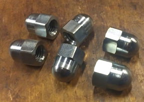
AT RIGHT: For those who may wish to "concourse" your efforts, in recognition that it's pretty much impossible to detail the case acorn nuts without disassembling the engine down to a short-block, beautiful acorn nuts were fitted!
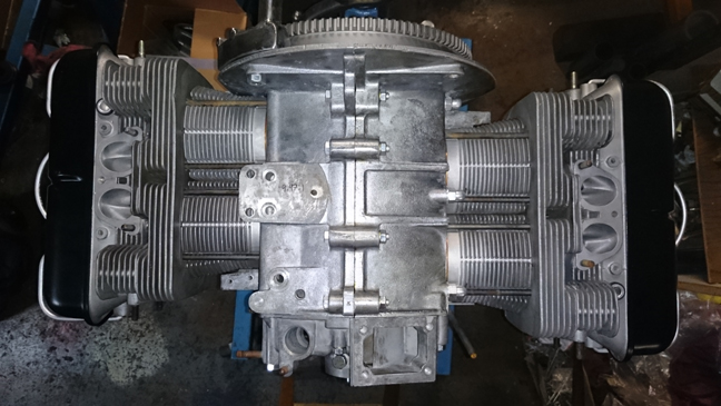
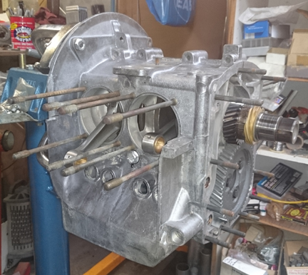
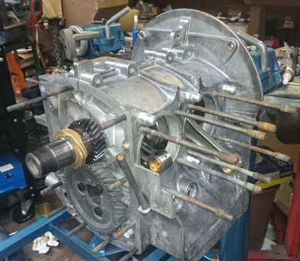
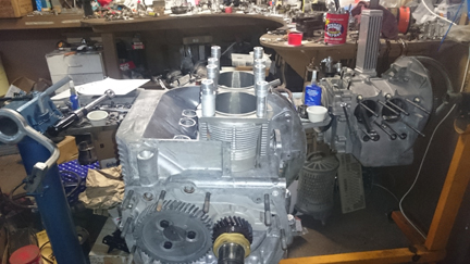
It looks like in my exhuberence, I managed to assemble the case halves without photographs of the lifters installed, etc., however, in these next images, we see the two halves which then get their timing cover mounted.
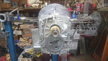
At this point, with the timing cover mounted, we can call it a true "short block."
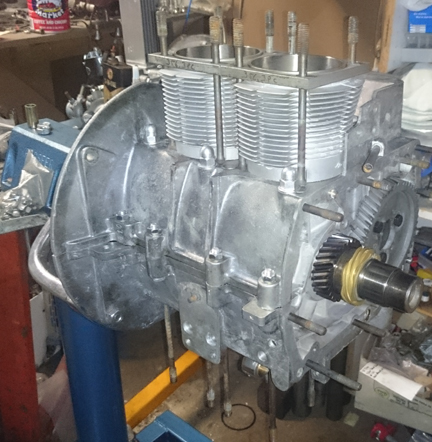
 Original SC / 912 cylinders
originally fitted to SC engines did not last as long as their all-iron counterparts
because in the process of manufacture, as the aluminum fins are cast on to the
iron, the iron is anealed, making it softer, and so they wear faster. In the
modern era, several manufacturers are making replacements that are also aluminum
fins over iron cylinders and they share the same wear issue, but at least they're
current manufacture! And, all of these of which we are aware are also "big
bore".
Original SC / 912 cylinders
originally fitted to SC engines did not last as long as their all-iron counterparts
because in the process of manufacture, as the aluminum fins are cast on to the
iron, the iron is anealed, making it softer, and so they wear faster. In the
modern era, several manufacturers are making replacements that are also aluminum
fins over iron cylinders and they share the same wear issue, but at least they're
current manufacture! And, all of these of which we are aware are also "big
bore".
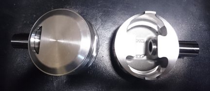
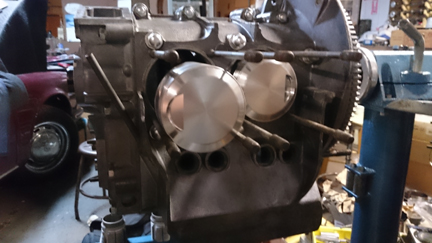
AT RIGHT: A pair of pistons which are going into this engine. They are forged big-bore (86mm), high compression (9.5:1) pistons fitted to biral cylinders (aluminum fins cast over iron) with a nickel plated wall. This is the best you can get! You'll see more of the cylinders in other images here.
However, we can overcome the wear problem by having the inside surface of the cylinder plated with nickel, increasing service life from, say, 60 to 80k miles, to perhaps several hundred thousand miles. Way back in the early 1950s, Porsche commissioned the vendor Mahle to make all aluminum cylinders and plate them with chrome, but chroming of aluminum is a rare thing today due to cost and environmental issues, so nickel is used instead - it's also very hard and gives very long service life. So, what we did here was get a set of the modern, big-bore birals and then nickel plated the cylinder's interior surface.
In addition, instead of a cast piston, we went with a forged, high-compression piston - stock compression, actually, for an SC, at 9.5:1.
So, even though they're beautiful, they went through a thorough checking process.
AT RIGHT: Trouble! In trial fitting, we immediatley found that none of the four cylinders would fit into the bore for cylinder 3! The fins struck the engine to transaxle mounting flange! The solution was to grind a tiny bit off of one cylinder.
We always check the match pistons to cylinders and match piston weights as a set, and provide any remedial action to correct any errors before installation. For example, by shuffling around the piston pins among the pistons, one can usually improve the matching of piston weights. This set naturally balanced (without removing material) to within 0.1 gram - the official specification is ten grams (10g). This is attributable to the piston manufacturer - they are very precise! (Note that there were at least four vendors involved in making this set: the cylinder manufacturer, the cylinder plater, the piston manufacturer, and ourselves, as we commissioned this work and put it together.)
 For
many shops, from this point, installation goes very quickly, but we think this
is where one needs to take one's time! The key reason one needs to take time
here is that there are production tolerances on every part in an engine, and
while a set of parts may look identical, there's often subtle variation between
members of a set, and there are sometimes significant errors in production
that weren't caught by the manufacturer's quality control processes. These errors
can "stack up" and cause problems if not discovered and corrected.
For
many shops, from this point, installation goes very quickly, but we think this
is where one needs to take one's time! The key reason one needs to take time
here is that there are production tolerances on every part in an engine, and
while a set of parts may look identical, there's often subtle variation between
members of a set, and there are sometimes significant errors in production
that weren't caught by the manufacturer's quality control processes. These errors
can "stack up" and cause problems if not discovered and corrected.
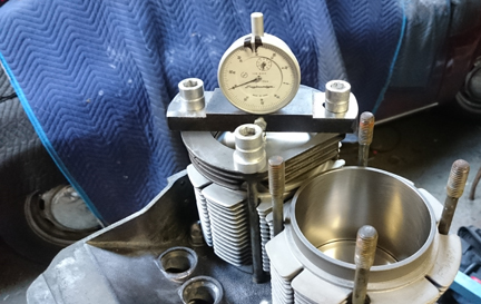
AT RIGHT: The right hand side cylinders (1 & 2) are about to undergo an installed Cylinder Height Check - or CHC, as described in the text. (See more about this in the caption to the other side's CHC below.)
Here's our process: Two of these steps require special tools most shops don't have.
 We
like to carefully measure everything and then mix-and-match the parts for superior
fit. We have also discovered significant manufacturing errors with this process
which would likely have gone unnoticed without these measures. It is remarkably
easy, for example, to overlook the circumstance of the crankshaft bore not in
the true center of the crankcase, angled on the horizontal left or right of
center, or not on the same horizontal plane at all. Yet examples of errors like
these are not as uncommon as we would like.
We
like to carefully measure everything and then mix-and-match the parts for superior
fit. We have also discovered significant manufacturing errors with this process
which would likely have gone unnoticed without these measures. It is remarkably
easy, for example, to overlook the circumstance of the crankshaft bore not in
the true center of the crankcase, angled on the horizontal left or right of
center, or not on the same horizontal plane at all. Yet examples of errors like
these are not as uncommon as we would like.
AT RIGHT: The left cylinder pair undergoing CHC. Note how the cylinders are retained with special spacers - these permit the cylinder to be held flat as it will be run in service and a check can be made to ensure that both cylinders top surfaces are in the exact same plane.The book value for tolerated error of installed cylinder height mismatch is 0.1mm (four thousandths of an inch), and this engine has zero difference between cylinders 1 and 2, and cylinder 3's inner edge was about 0.03mm (between 0.001" and 0.0015") low, canting it slightly toward cylinder 4.
 The
methods by which we accomplish these steps involve steps nobody else does
(that we know of) in the engine building process, and that is to measure
the height the piston crown comes above the plane of the top of the cylinder.
I call this the CAC, or "Crown Above Cylinder." This value is important
because, firstly, it can reveal deeper problems, and because it helps us get
the compression ratio equal in all four cylinders.
The
methods by which we accomplish these steps involve steps nobody else does
(that we know of) in the engine building process, and that is to measure
the height the piston crown comes above the plane of the top of the cylinder.
I call this the CAC, or "Crown Above Cylinder." This value is important
because, firstly, it can reveal deeper problems, and because it helps us get
the compression ratio equal in all four cylinders.
AT RIGHT: Cylinder 2 undergoing its CAC.
Here are some of the deeper problems that can be discovered through a CAC check:
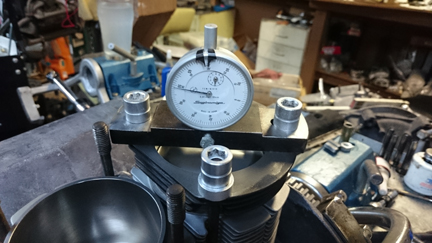 AT
RIGHT:Cylinder 3 having its CAC value measured. All four cylinders are
measured this way, and should any significant difference be found between
cylinders, swapping pistons, cylinders or even heads around can help make
a better compression ratio match - or simply find out exactly where any
discrepancy may lie. This measure is extraordinarily accurate.
AT
RIGHT:Cylinder 3 having its CAC value measured. All four cylinders are
measured this way, and should any significant difference be found between
cylinders, swapping pistons, cylinders or even heads around can help make
a better compression ratio match - or simply find out exactly where any
discrepancy may lie. This measure is extraordinarily accurate.
In order to do this for these engines, you have to have special tools. Here, you can see them in action on these images which document the "CHC" and "CAC" steps.
The distance between the smallest tick marks is one hundredth of a mm, or 0.0004", and you can discern to perhaps a tenth of that! So, this is a very accurate measure, performed while the cylinder is under torque, so any shims are squished flat, etc. In terms of the CAC value, it is better to consider its effect on combustion chamber volume rather than thinking of it as a length.
 The
accuracy of this measure is so good, that if you take the time to swap parts
around, you can accurately determine discrepancies in the manufacture of the
various parts! But, we ARE splitting hairs here! However, a benefit to both
engine builder and customer is that the ability to move parts around for better
fit means that perfection is more easily achieved, and the more equal the HP
production of each cylinder, the smoother the engine will run, and the more
HP the engine will produce overall.
The
accuracy of this measure is so good, that if you take the time to swap parts
around, you can accurately determine discrepancies in the manufacture of the
various parts! But, we ARE splitting hairs here! However, a benefit to both
engine builder and customer is that the ability to move parts around for better
fit means that perfection is more easily achieved, and the more equal the HP
production of each cylinder, the smoother the engine will run, and the more
HP the engine will produce overall.
AT RIGHT: Here we see that the shop that nickel plated the cylinders has numbered each cylinder individually.
Because this process includes the entire assembly, torqued as in service, and measures the height each piston protrudes out of its cylinder, any and all errors in connecting rod lengths, cylinder heights, crankcase spigots depths (cylinder bore deck), piston connecting pin heights, and shim thickness' are accounted for in the measurement results. There is no superior method.
 The
heads looked pretty good, as was, but as stated elsewhere, our goal is to have
a consistent, reliable product, so I replaced all the valve guides, used new
higher-tension springs, re-faced the valves, ground & lapped the valve seats,
and then carefully assembled the valves onto the heads paying special attention
to spring-heights.
The
heads looked pretty good, as was, but as stated elsewhere, our goal is to have
a consistent, reliable product, so I replaced all the valve guides, used new
higher-tension springs, re-faced the valves, ground & lapped the valve seats,
and then carefully assembled the valves onto the heads paying special attention
to spring-heights.
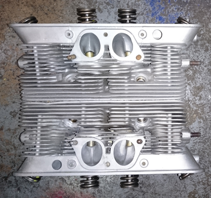
AT RIGHT: The heads, ready for installation. No broken fins, only one "ding", visible here on the bottom head, left side, fin closest to cylinders.
Note that these are great valves. They're originals, not aftermarket replacement which are all you can get new today. Further, and vitally, the exhaust valves ARE the sodium filled type, which haven't been available new for some years now. Of course, the valves have been checked for length (stretching makes them unworthy), refaced, and stems polished, so they're effectively perfect.
We went through a batch of about 32 new springs and they were grouped by strength. We match up slightly stiffer springs with the heavier valves (intakes are about 2% heavier than exhausts), so they're very close sets, matched up, so all the valves tend to float at the same time. ...Of course, each valve and retainer are position-specific through the shimming process as the spring-heights are set. This close-matching of spring tensions helps the driver know when they're over-revving because all the valves will tend to float at exactly the same time, thus sending the clear signal of a drop-off in power. When one or two valves float before the others, the driver may not realize they're harming the engine and continue on, getting into trouble!
 The
springs are also a bit stiffer than stock. The stock closing pressure was about
68 lbs, but experience has shown that sometimes when someone might over-rev
the engine, a piston can strike an exhaust valve with very negative consequences.
Modern professionals know this and install stiffer springs.
The
springs are also a bit stiffer than stock. The stock closing pressure was about
68 lbs, but experience has shown that sometimes when someone might over-rev
the engine, a piston can strike an exhaust valve with very negative consequences.
Modern professionals know this and install stiffer springs.
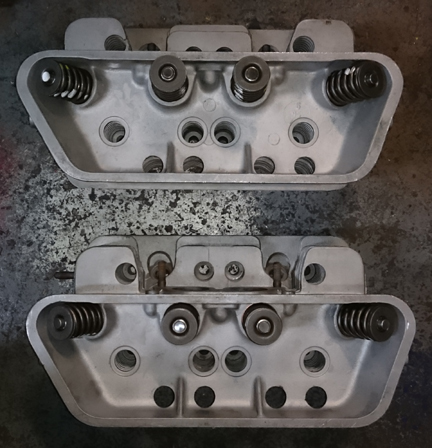
AT RIGHT: The heads are "early 912", ready for installation...
At this point the engine is ready for its cylinder heads, and this work went very quickly - as it should! - as all the prep work was already done.
Prepare the head "bolts" and washers, prepare the pushrod tubes, prepare the lower cylinder air deflection plates and their wire retainers, and get the torque wrenches set, and bolt on those heads!
My pattern is to mount one head, torque it to 7 ft lbs, then mount the other head the same way, and then alternate between the heads with an ever-increasing torque up to the final torque value, then repeat the final torque value until the fasteners no longer turn when torque is applied.
Then, mount the valve gear, adjust the valves and pop on the valve covers. Yeah, sounds simple, but, to do a great job, there's more to it than that...
...The careful engine builder is constantly running into problems like either worn out rocker arm contact faces (where they contact the valve stem), or mis-ground by someone who didn't have the wherewithall to grind them properly, as happens all too often, and as can be seen here.
As stated elsewhere, we take special care to do a really great job, and one detail that is very often overlooked are the rocker arms where they contact the valve stem. These parts are surface hardened by the factory, but once that's worn through, the rate of wear goes up considerably and metal particles get introduced into the engine oil. Therefore, we hard-face every rocker. In this process, new material is welded on to the rocker's valve contact face and then the face is re-machined to the proper curve and smoothness. This not only repairs worn out rockers, but it's also a bit better than stock, too, because the "hard face" material is super tough, harder than the original rockers were.
...I decided to solve the problem permanently by applying "hard face" to the contact surfaces, as can be seen here.
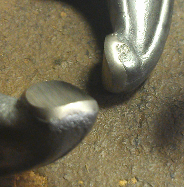
BELOW LEFT: Larger than real-life close-up showing the new material having been applied to the rocker's contact faces and then properly ground. These rockers won't wear like the originals did - this should be a "lifetime fix" for most engines! And, it also helps lengthen the life of valves by reducing wear on the valve stem caused by an uneven rocker contact face.
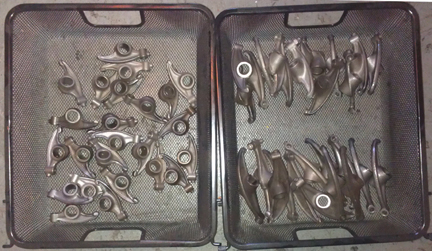
BELOW RIGHT: Yes, doing them in large batches is MUCH more economical. This is about seven engines worth. And yes, the set in this engine came from the baskets shown here!
A SMALL point, but important: EVERY engine gets all new valve adjustment jamb nuts!
Then, fit the two oil control pistons.
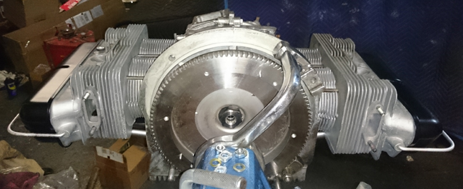
And now here it is as the longblock, ready for pickup or delivery!