Copyright © 2007 - 2024, Coachworks For contact data Click Here.
Copyright © 2007 - 2024
Copyright © 2007 - 2024,
Coachworks For contact data
Click Here.
![]() has been retained for reference purposes.
has been retained for reference purposes.
 Porsche
Engine
Porsche
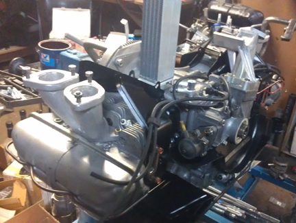
EngineAT RIGHT:Almost ready - the oil pump was still in the parts washer when this image was taken!
This engine has been prepared in long-block form, but may be purchased complete, ready to install, with only a few days delay.
This engine is optionally available Run-In on our Stuska water-brake engine dynamometer as per Porsche factory specifications as outlined in the Workshop Manual, operations 52 EN, 53 EN, and 54 EN, pages E83 and E84. You can see this being performed on another of our engines here - see the second image down.
This 356 SC engine has just undergone a complete overhaul, and is fully balanced for smooth running, long life, and a few more HP.
This engine has all the equipment that Porsche itself would have provided as an SC replacement engine under the KD program during the era in which the crankcase was constructed, with the exception of big-bore pistons and cylinders. The cylinders are, however, "biral" (aluminum fins over an iron liner), just as the originals were.
This engine has no type numbers or "casting number" stamped into the main half pairs, and no serial number stamped into the timing cover. The only numbers stamped in the case are the "match numbers" used to ensure that parts which were machined together remain together. The month of casting was cast into the case halves are February (right half) and March (left half), 1969. This was near the end of the 912 era, so it has all the best improvements, and Porsche machined the timing cover for service in 356 automobiles, as was done for all 356 replacement cases after 356 production ended in 1965.
During this rebuild every detail has been attended to; nothing was ignored.
 Background
on This Engine
Background
on This Engine
One of us assembled this engine over 23 years ago and it served as as a spare engine for a Porsche collector. As such, it was seldom used - that's just dust on it! Unfortunately, earlier history on this engine has been lost. However, it only served a few thousand miles in service during all that time. Dispite the low mileage on the previous rebuild, we went through it again, valve cover to valve cover! The idea here is to provide customers a consistent, dependable product, not trust what was done decades ago.
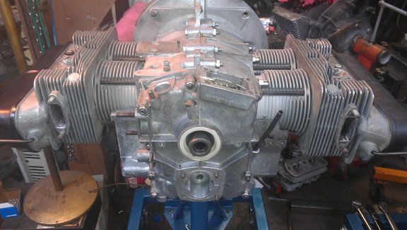
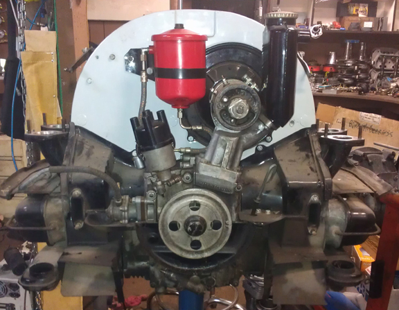
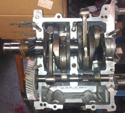
AT RIGHT: This engine during the tear down process and after 20 years as the "spare engine" . Note the late Solex manifolds and the C / SC breather with smaller ("6V") generator.
 AT
RIGHT : Here you can see the places where the engine's type numbers and
serial number were stamped - but there are no stamps whatsoever. Also note that
very late 912 heads were fitted. Note the air-injection port areas of the late
head casting have never been drilled; these are stock 912 heads made after the
air-injection system was abandoned, and are precisely what Porsche would have
fitted to a KD engine serviced in March of 1969.
AT
RIGHT : Here you can see the places where the engine's type numbers and
serial number were stamped - but there are no stamps whatsoever. Also note that
very late 912 heads were fitted. Note the air-injection port areas of the late
head casting have never been drilled; these are stock 912 heads made after the
air-injection system was abandoned, and are precisely what Porsche would have
fitted to a KD engine serviced in March of 1969.
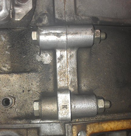
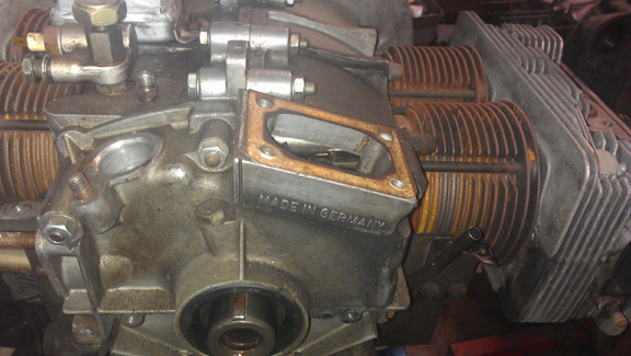
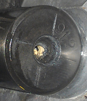
AT RIGHT: A close-up of the locations where the "case casting number" and engine type numbers are stamped. As can be seen, no numbers were ever stamped on this case in these locations.
 Crankcase
Preparation
Crankcase
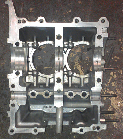
Preparation This crankcase cleaned up nicely and didn't need any special preparation before reassembly. The case was previously align-bored to first oversize and is virtually perfect.
AT RIGHT: Just lovely - all nice and sparkly clean! Near perfection.
Apparently I overlooked taking images of the left half bare, however, you can see it's just as nice in the images in the assembly section (below).
 The
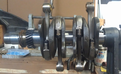
crankshaft is a genuine "SC / 912" crank and was checked for cracks
and rotationally balanced on its own.
The
crankshaft is a genuine "SC / 912" crank and was checked for cracks
and rotationally balanced on its own.
As usual, I rebuilt the connecting rods. I did not track which set was which, I just put the used ones into the pipeline to be redone, and when ready, grabbed one of these sets at right. All these are "late type", the best of the breed. All have been rebuilt carefully. I rebuild rods in batches - it's easier / faster / cheaper that way as it keeps setup time to a minimum.
 AT
RIGHT: This engine's crankshaft with rods attached. Note that new nuts were
fitted.
AT
RIGHT: This engine's crankshaft with rods attached. Note that new nuts were
fitted.
For me, "rebuilding the rods" means to:
This is all standard work so there aren't any photos of them in-process.
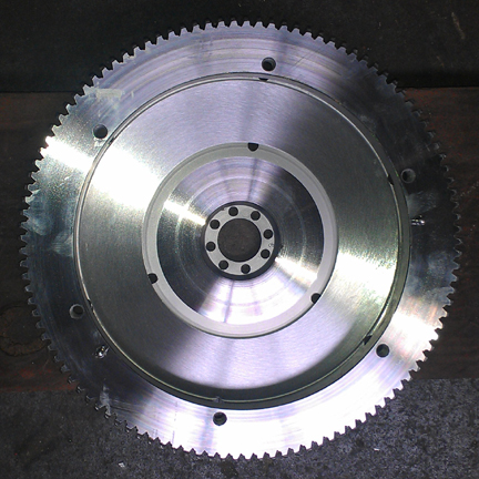
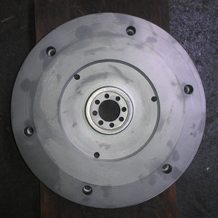
The flywheel is a stocker (200mm, 6v ring gear) that needed refacing. Here it is, done:
In the trial assembly, everything went perfectly.
 As
this is an SC engine, the most awesome of the 356 pushrod engines, I wanted
to make certain everything inside the case is nothing but the best. So, I selected
a camshaft that Porsche itself would have fit: It is an old-school Porsche shaft
which has been reground to the same specifications it was when new! Namely,
"SC/912". It was then parkerized (see note on parkerization below).
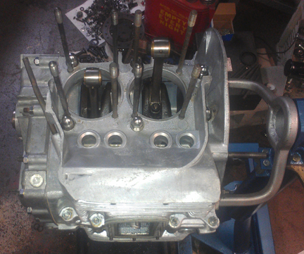
The cam followers were refaced, of course, though it was probably unnecessary
- you can see them lurking below the cam lobes in these images...
As
this is an SC engine, the most awesome of the 356 pushrod engines, I wanted
to make certain everything inside the case is nothing but the best. So, I selected
a camshaft that Porsche itself would have fit: It is an old-school Porsche shaft
which has been reground to the same specifications it was when new! Namely,
"SC/912". It was then parkerized (see note on parkerization below).
The cam followers were refaced, of course, though it was probably unnecessary
- you can see them lurking below the cam lobes in these images...
AT RIGHT: Here the camshaft gear was just selected. It's an iterative process of trying gears until one of them works well!
Parkerizing is a hardening process which eliminates any "need" to over-rev the engine to work-harden the cam lobes. (If anyone ever tells you you must rev your freshly rebuilt engine to high-rpm in order to work-harden the camshaft lobes, you've chosen the wrong parts vendor / cam grinder! This should never be required! If you're racing, that's one thing, but most of us can afford the normal, gentle run-in process that results in a long-lived engine...)
BELOW LEFT: The cam grinder was kind enough to mark the grind he put on the cam. It's usually put on the gear end so it can be seen with the timing cover off, but in this case "it's going back to what it already was," so that may have seemed unnecessary.
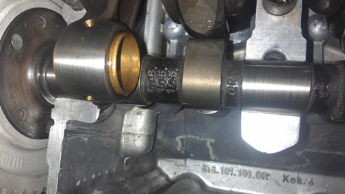
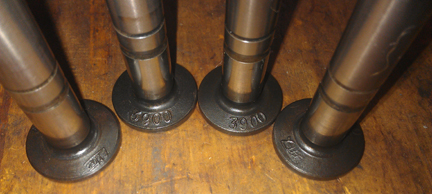
ABOVE RIGHT: Here are the numbers identifying the cam billet... and a nice shot of the wrist pin bushing for cylinder two!
BELOW: It occurred to me that seldom are the lifers shown - so here are a couple of shots of them:
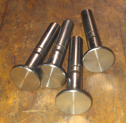
These four went into the right half!
 Now,
time to put the case halves together! Prep-work done correctly, this goes easily
and quickly and the story is best told in images.
Now,
time to put the case halves together! Prep-work done correctly, this goes easily
and quickly and the story is best told in images.
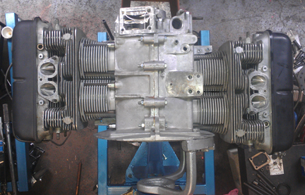
I didn't pause, apparently, to take photos of the two halves together without the timing cover - it goes rather quickly, the timing cover goes on, and so here we have it as a "bottom end:"
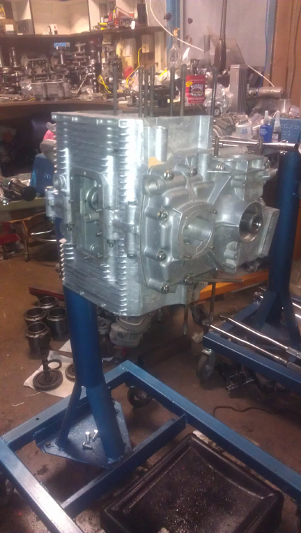
AT RIGHT:We have a "short-block"! Note how the case just gleams! Even the timing cover is pretty! Note hte large oil pump, of course! Also note all the new hardware. And, there are three sump-studs not installed. That's covered later.
ABOVE LEFT: The right case half went straight on, torqued up easily, no issues whatsoever, fitted the parimeter bolts, then -zlot!- on went the timing cover!
When it comes to engine building, one of my motos is:
Clenliness is next to Godliness!
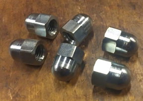
AT RIGHT: For those who may wish to "concourse" your efforts, in recognition that it's pretty much impossible to detail the case acorn nuts without disassembling the engine down to a short-block, new acorn nuts were fitted!
There's a bit more to do... Like the sump studs! Several had come out during disassembly. Investigation showed no problem with them, they just didn't stay in the case! So, a bit of Loc-tite thread-locking compound...
ABOVE LEFT AND RIGHT: On left, note the blue around the base of the sump studs - that's the Loc-tite thread locking compound. It tends to ooze out as you thread in a fastener. Afterwards, the height of each stud is carefully set (10mm), and the excess locking compound is wiped away. ...Note also how CLEAN it is inside that case! Every engine assembly should be this clean.
Then fit the oil drain plug, and sump screen and plate. Of some small note is that all the sump studs are original and in fine condition. I used new cap-nuts on the oil sump studs to protect the studs into the future - they're vulnerable to road debris.
 Pistons
and Cylinders
Pistons
and CylindersOriginal SC / 912 cylinders originally fitted to SC engines did not last as long as their all-iron counterparts because in the process of manufacture, as the aluminum fins are cast on to the iron, the iron is anealed, making it softer, and so they wear faster. In the modern era, several manufacturers are making replacements that are also aluminum fins over iron cylinders and they share the same issue, but at least they're current manufacture! And, all of these of which we are aware are also "big bore" - basically NPR copies, but with biral cylinders. As they're the best similar item we can get today, that's what was installed here.
AT RIGHT: The cylinders going into this engine, 86mm birals, cleaned and honed, ready for installation.
So, the ones fitted to this engine now are modern birals with a larger bore. They're 86mm, and they're beautiful.
We always check the match pistons to cylinders and match piston weights as a set, and provide any remedial action to correct any errors before installation. For example, by shuffling around the piston pins among the pistons, one can usually improve the matching of piston weights. This set naturally balanced (without removing material) to +/- 0.2 grams - the official specification is ten grams (10g). Oops, make that almost - some material was removed from one pin to get that balance!
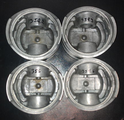
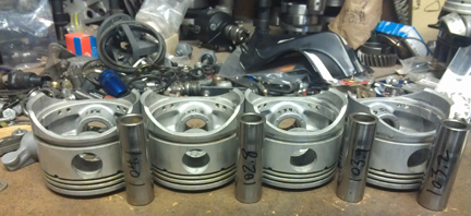
AT LEFT AND ABOVE RIGHT: This set of pistons and cylinders has had very little use, but is receiving a new set of rings, and is being balanced carefully. Note the starting weights taken at the beginning of the balancing process, in grams, are written on the pieces. YES, one piston, bare, happened to weigh 356 grams exactly!
 For
many shops, from this point, installation goes very quickly, but we think this
is where one needs to take one's time! The key reason one needs to take time
here is that there are production tolerances on every part in an engine, and
while a set of parts may look identical, there's often subtle variation between
members of a set, and there are sometimes significant errors in production
that weren't caught by the manufacturer's quality control processes. These errors
can "stack up" and cause problems if not discovered and corrected.
For
many shops, from this point, installation goes very quickly, but we think this
is where one needs to take one's time! The key reason one needs to take time
here is that there are production tolerances on every part in an engine, and
while a set of parts may look identical, there's often subtle variation between
members of a set, and there are sometimes significant errors in production
that weren't caught by the manufacturer's quality control processes. These errors
can "stack up" and cause problems if not discovered and corrected.
Here's our process: Two of these steps require special tools most shops don't have.
We like to carefully measure everything and then mix-and-match the parts for superior fit. We have also discovered significant manufacturing errors with this process which would likely have gone unnoticed without these measures. It is remarkably easy, for example, to overlook the circumstance of the crankshaft bore not in the true center of the crankcase, angled on the horizontal left or right of center, or not on the same horizontal plane at all. Yet examples of errors like these are not as uncommon as we would like.
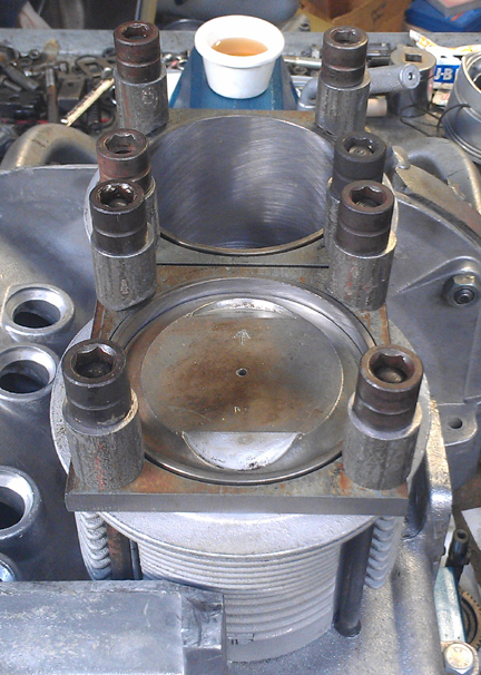
AT RIGHT: Here you can see the height comparison check (for cylinders 3 and 4) - this is done to ensure that there are no difference between the cylinder heights that the head itself "sees." The book value for tolerated error is 0.1mm (four thousandths of an inch), and this engine has zero difference between cylinders 1 and 2, and about 0.063mm (about two and a half thousandths of an inch) between cylinders 3 and 4.
 The
next thing we do is something nobody else does (that we know of) in the
engine building process, and that is to measure the height the piston crown
comes above the plane of the top of the cylinder. I call this the CAC, or
"Crown Above Cylinder." This value is important because, firstly,
it can reveal deeper problems, and because it helps us get the compression ratio
equal in all four cylinders.
The
next thing we do is something nobody else does (that we know of) in the
engine building process, and that is to measure the height the piston crown
comes above the plane of the top of the cylinder. I call this the CAC, or
"Crown Above Cylinder." This value is important because, firstly,
it can reveal deeper problems, and because it helps us get the compression ratio
equal in all four cylinders.
Here are some of the deeper problems that can be discovered through a CAC check:
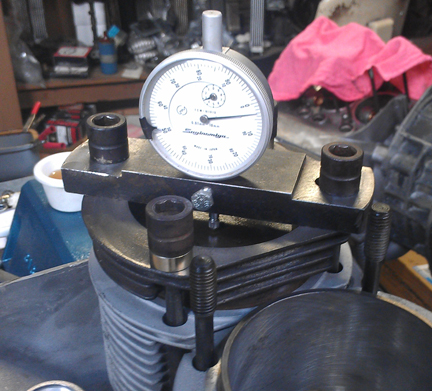
AT RIGHT:Cylinder 3 having its CAC value measured. All four cylinders are measured this way, and should any significant difference be found between cylinders, swapping pistons, cylinders or even rods around can help make a better match and find out exactly where the discrepancy may lie. This measure is extraordinarily accurate.
In order to do this for these engines, you have to have special tools. Here, you can see them in action on these images.
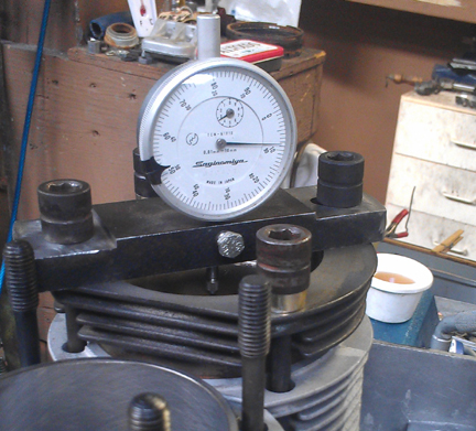 The
distance between the smallest tick marks is one hundredth of a mm, or 0.0004",
and you can discern to perhaps a tenth of that! So, this is a very accurate
measure, performed while the cylinder is under torque, so any shims are squished
flat, etc. In this instance, the heights at which the pistons protrude above
the plane of the top of the cylinders were all remarkably close, within 0.07mm,
well within tolerance, which, in this case, is better measured in its effect
on combustion chamber volume than as a length. In any event 0.07mm is among
the closest you'll find from parts that have not especially been "blueprinted"
to perfection.
The
distance between the smallest tick marks is one hundredth of a mm, or 0.0004",
and you can discern to perhaps a tenth of that! So, this is a very accurate
measure, performed while the cylinder is under torque, so any shims are squished
flat, etc. In this instance, the heights at which the pistons protrude above
the plane of the top of the cylinders were all remarkably close, within 0.07mm,
well within tolerance, which, in this case, is better measured in its effect
on combustion chamber volume than as a length. In any event 0.07mm is among
the closest you'll find from parts that have not especially been "blueprinted"
to perfection.
The accuracy of this measure is so good, that if you take the time to swap parts around, you can accurately determine discrepancies in the manufacture of the various parts! But, we ARE splitting hairs here! However, a benefit to both engine builder and customer is that the ability to move parts around for better fit means that perfection is more easily achieved, and the more equal the HP production of each cylinder, the smoother the engine will run, and the more HP the engine will produce overall.
Because this process includes the entire assembly, torqued as in service, and measures the height each piston protrudes out of its cylinder, all errors in connecting rod lengths, cylinder heights, crankcase spigots depths (cylinder bore deck), piston connecting pin heights, and shim thickness' are accounted for in the measurement results. There is no superior method.
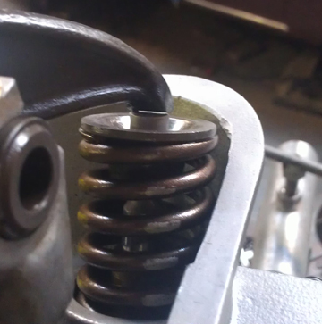
 The
heads looked really great, and were probably perfect, except that the springs
have been in compression for something like 20 years and have, no doubt, relaxed
some tension. As stated elsewhere, the idea is to have a consistent, reliable
product, so I replaced all the valve springs with new, re-faced the valves,
ground & lapped the valve seats, and then carefully assembled the valves
onto the heads paying special attention to spring-heights.
The
heads looked really great, and were probably perfect, except that the springs
have been in compression for something like 20 years and have, no doubt, relaxed
some tension. As stated elsewhere, the idea is to have a consistent, reliable
product, so I replaced all the valve springs with new, re-faced the valves,
ground & lapped the valve seats, and then carefully assembled the valves
onto the heads paying special attention to spring-heights.
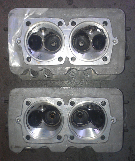
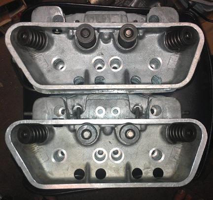
AT RIGHT: The heads after preliminary cleaning only! They got more attention later.
Note that these are great valves. They're originals, not aftermarket replacement which are all you can get new today. Further, and vitally, the exhaust valves ARE the sodium filled type, which haven't been available new for some years now. Of course, the valves have been checked for length (stretching makes them unworthy), refaced, and polished, so they're effectively perfect.
We went through a batch of about 32 new springs and they were grouped by strength. We match up slightly stiffer springs with the heavier valves (intakes are about 2% heavier than exhausts), so they're very close sets, matched up, so all the valves tend to float at the same time. ...Of course, each valve and retainer are position-specific through the shimming process as the spring-heights are set. This close-matching of spring tensions helps the driver know when they're over-revving because all the valves will tend to float at exactly the same time, thus sending the clear signal of a drop-off in power. When one or two valves float before the others, the driver may not realize they're harming the engine and continue on, getting into trouble!
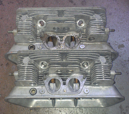
BELOW LEFT: The heads following preliminary cleaning - I wouldn't have used this image normally because you can see that one of the intake manifold gaskets got stuck (it was later razor-bladed off!) but I forgot to take images later, except, of course, after assembly was complete. Also note both "912 breather block-off plugs" are like new - they were left in place since they didn't need any attention.
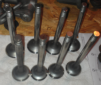
ABOVE RIGHT: The actual valves selected for this engine.
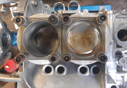
BELOW LEFT AND RIGHT: After the valves are fitted, the combustion chambers are measured with a burrette, and marked for each cylinder (in ml).
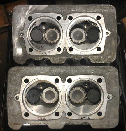
Note that the "dot" (divot) in the center of the exhaust valves (outboard) is used to denote sodium is contained therein.
At this point the engine is ready for its cylinder heads, and this work went very quickly - as it should! - as all the prep work was already done.
Prepare the head "bolts" and washers, prepare the pushrod tubes, prepare the lower cylinder air deflection plates and their wire retainers, and get the torque wrenches set, and bolt on those heads!
My pattern is to mount one head, torque it to 7 ft lbs (as per the manual), then mount the other head the same way, and then alternate between the heads with an ever-increasing torque up to the final torque value, then repeat the final torque value until the fasteners no longer turn when torque is applied.
OK, mount the valve gear, adjust the valves and pop on the valve covers. Yeah, sounds simple, but, to do a great job, there's more to it than that...
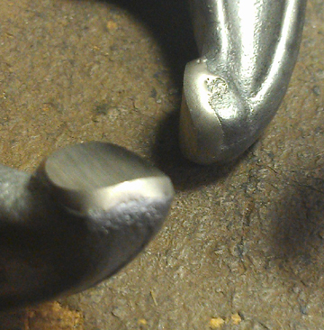
...The careful engine builder is constantly running into problems like either worn out rocker arm contact faces (where they contact the valve stem), or mis-ground by someone who didn't have the wherewithall to grind them properly, as happens all too often, and as can be seen here.
BELOW LEFT: Here's a mis-ground rocker arm someone "refaced" in the past. Note how the rocker is only making contact on the extreme left edge of the valve stem! The result of this situation is both excessive wear of the valve stem and also that a "pocket" develops on the rocker arm, making valve adjustments difficult! The rocker was, no doubt, refaced "by hand".
BELOW RIGHT: Original rockers with too much wear. It's hard to see in these images, but there are spots where the curve on the rockers is pitted and worn and the action opening and closing the valve would not be smooth. And, checking adjustment is harder than it should be because the surface isn't smooth, so it's easy to get false readings.
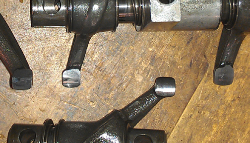
...I decided to solve the problem permanently by applying "hard face" to the contact surfaces, as can be seen here.
BELOW LEFT: Larger than real-life close-up showing the new material having been applied to the rocker's contact faces and then properly ground. These rockers won't wear like the originals did - this should be a "lifetime fix" for most engines! And, it also helps lengthen the life of valves by reducing wear on the valve stem caused by an uneven rocker contact face.
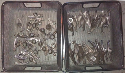
BELOW RIGHT: Yes, doing them in large batches is MUCH more economical. This is about seven engines worth. And yes, the set in this engine came from the baskets shown here!
BELOW: Of course, fantastic adjustment screws - can't forget them! ...In this image, they're actually larger than they are in real life!
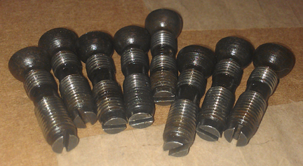
A SMALL point, but important: EVERY engine gets all new valve adjustment jamb nuts! See them in the images below.
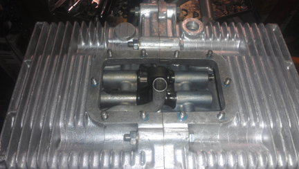
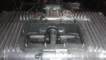
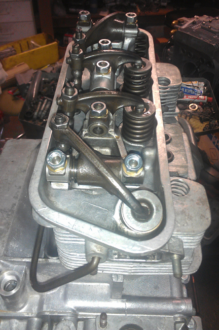
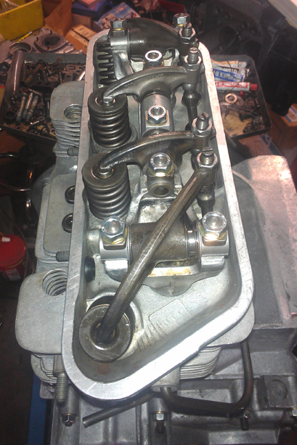
BELOW RIGHT AND LEFT: Here we see the completed valve train - the left image is the left side (cylinders 3 and 4) and the right image is the right side (1 and 2).
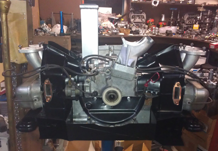
 AT
RIGHT: Here's the completed longblock. ...Almost. The flywheel will be mounted
after it's taken down from the engine stand. Note there's celophane capping
both the oil cooler mount and generator stand openings, as a precaution. (Other
openings will be sealed later.)
AT
RIGHT: Here's the completed longblock. ...Almost. The flywheel will be mounted
after it's taken down from the engine stand. Note there's celophane capping
both the oil cooler mount and generator stand openings, as a precaution. (Other
openings will be sealed later.)
Then, fit the two oil control pistons.
And now here it is as the longblock, ready for pickup or delivery!
So, of course this wonderful engine was purchased. The customer provided a core engine from which the "accessores" were moved from the one engine to the other. The following images tell that story and the subsequent running on our Dynamometer followed by installation into the vehicle - a 1957 Carrera!
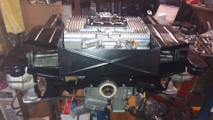
The sheet metal was powder-coated, of course! And, an aluminum cooler was sourced.