Copyright © 2007 - 2024, Coachworks For contact data Click Here.
Copyright © 2007 - 2024
Copyright © 2007 - 2024,
Coachworks For contact data
Click Here.
![]() has been retained for reference purposes.
has been retained for reference purposes.
This engine, complete, is ready for pickup or delivery today.
This engine has just undergone a complete overhaul.
The crankcase is "numbers matching" and not yet line-bored to first over. It has the late-type oil pump, late rockers, late B heads, etc. It is fitted with original Mahle high-compression, long skirt pistons and has its compression ratio set to 8.5:1, as per original specifications.
Every detail about the engine has been attended to, as outlined below; nothing was left unattended to.
I received this engine from George Walling and his father John. John, now in his 90s, used to run a Porsche repair facility in southern Oregon back in the 1960s. George owns a 1955 Speedster (original owner) and used the engine featured here in partial trade for this other engine for his Speedster..
This engine was the last of the rebuilds John had performed, decades ago. It didn't turn over and nobody knew why.
 Here
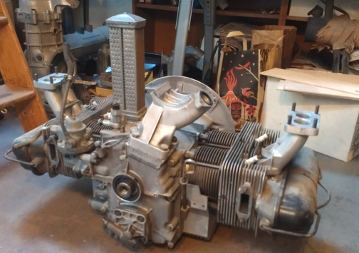
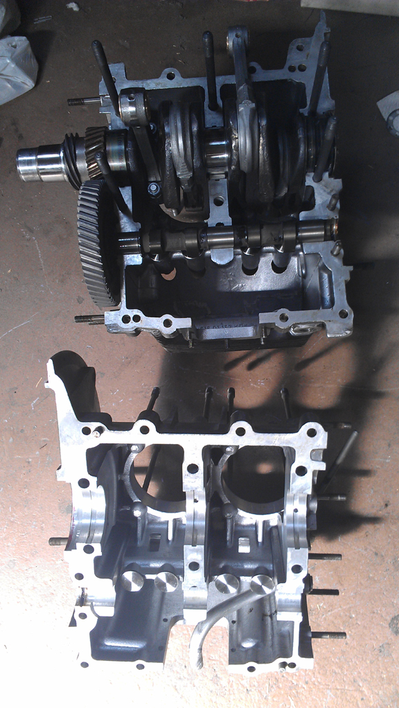
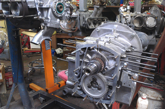
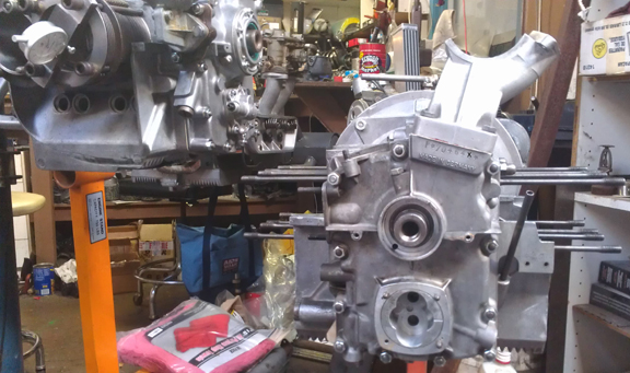
is the engine as I received it (above right). It would be on an engine stand
except all SIX of them are all already occupied! . . . .
Here
is the engine as I received it (above right). It would be on an engine stand
except all SIX of them are all already occupied! . . . .
Here it is as a long-block, ready for pickup or delivery (below right):
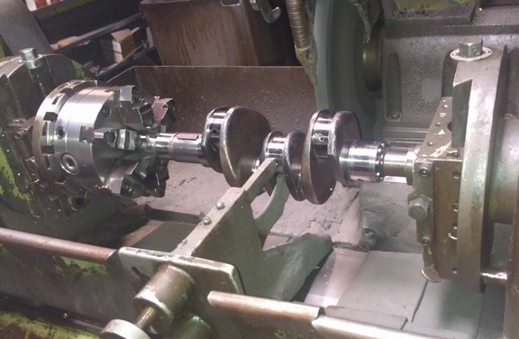
The first thing to do was to figure out why it didn't turn over. I expected a mis-aligned main bearing had been clamped down on a dowel-pin, but that wasn't the case. Figuring it out took some real doing because it was an unusual cause: whoever the machinist was who worked on this engine had screwed up and the middle main journal was siezing up. (More on this below.)
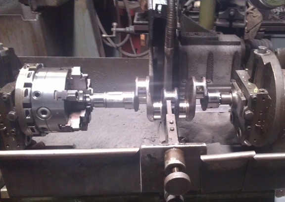
Thankfully, a friend of mine has a crankshaft grinder and we re-ground this one journal that was too large (see above) - bearing #2, also known as "the middle main." Now how many people are going to grind just ONE journal?! If that's what's needed, that's what we do. Here you can see that operation happening - first, intall the crank into the grinder and get the steady-rest (effectively a buck) up against the crank, so it won't flex while grinding:
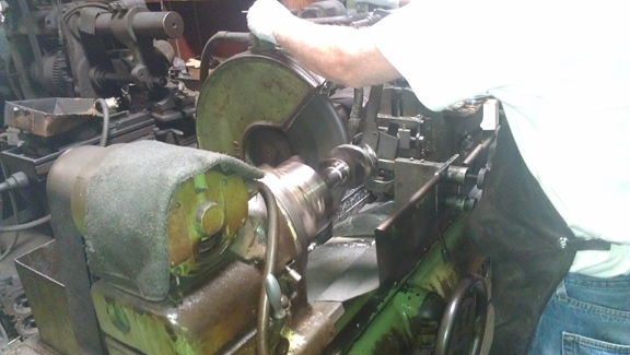
Now, setup the measurement:
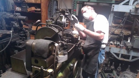
Next, get the grinding stone in alignment.........
And now grind it!
Following this, the crank was polished, then thoroughly cleaned.
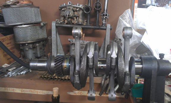
Meanwhile, John hadn't done anything to the connecting rods. That's not to our style. So, I "rebuilt them."
For us, "rebuilding the rods" means to:
This is all standard work so there aren't any photos of them in-process. However, here they are when assembled onto the crankshaft:
The crankcase was in pretty good condition. It hasn't yet been bored to first over-size, so it's got a lot of life left in it.
The oil pickup tube had been a little man-handled, though, apparently to put on an extension for an extended sump and it was a bit lose in the case. They were originally swaged into place, but re-swaging them seldom (if ever) works. My first solution was to attempt to seal it (and effectively glue it in place) with case sealant. Sometimes, if it's not very loose, this works, but this one was too loose and with no way to cure the case sealant (it's usually cured by either heat or time), this wasn't satisfactory.
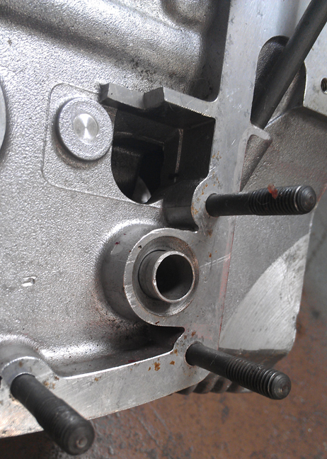
My second and permanent solution was quite simple; I followed the technique used in the later crankcases in which the tube is not swaged, but left floppy in the case, and fitted an o-ring around the tube where it enters the third piece. The o-ring is forced to distort into a triangular shape and in so doing it both clamps the tube in place so it can't rotate and also makes a great air-tight seal (remember, it's drawing, so an air-leak would permit it to draw air instead of oil). A bit of a bevel on one side and flat on the other, and the o-ring is crushed into the pickup-tube and you're done. The factory solution used on younger engines puts the bevel on the right main case half, but in this instance it was easier to put the bevel into the timing cover because the pickup tube itself was in the way, and previously swaged, it wasn't easily removed.
Unfortunately, when the time came, I forgot to take a picture of this! But here it is on a later crankcase, so you can see what it's all about - imagine this bevel on the 3rd piece side and there you have it!
Allright, back to the main case halves. I hate working on the workshop floor, but all six of the engine stands were in service and at least the floor is painted.
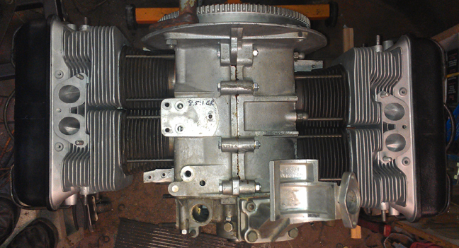
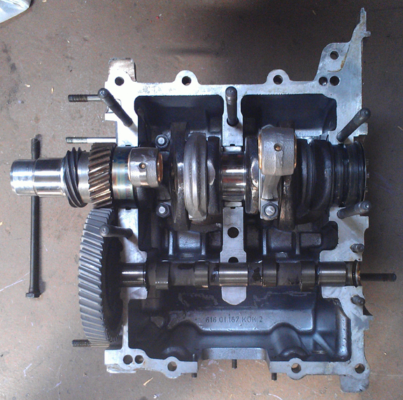
I often take photographs of the insides of the bare crankcase, but as I wrote above, things progressed very quickly and I nearly overlooked taking any such photographs. However, I did think of it just before sealing the halves together and took a few photos. Here is the case (almost) ready for sealant:
...I said "almost" - the right half of the middle-main still had to be installed, as did the camshaft end-plug. Note in the image above you can just make out the o-ring mounted on to the oil pickup tube protruding through the right case half on the far right - it looks almost in-line with the lifters in this image. Those dark spots on the bottom of the inside of the case is a little bit of case sealant that I'd attempted to use to "glue" the oil pickup tube into position, as described above.
It's worth pointing out here that John had put in a used camshaft and it was on the edge of too-much wear. I opted for a freshly ground cam out of my stock - it's the 912 grind on an original "narrow lobe" 1600S casting - and it has been "parkerized", a hardening process which eliminates any "need" to over-rev the engine to work-harden the cam lobes. (If anyone ever tells you you must rev your freshly rebuilt engine to high-rpm in order to work-harden the camshaft lobes, you've chosen the wrong parts vendor / cam grinder! This should never be required! If you're racing, that's one thing, but most of us can aford the normal, gentle run-in process that results in a long-lived engine...)
Also worth pointing out here are the refaced cam followers.
Yes, those are Kolbenschmidt bearings - old-school... You can just make out the ink markings that denote their size and part numbers.
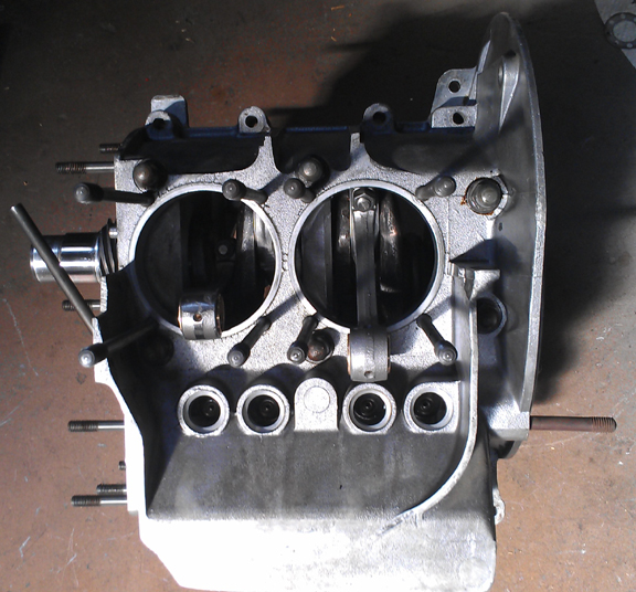
Here's a better image of the left side:
Here's the bottom bolted together, still awaiting the parimeter bolts to be attached:
The heads looked really great, however, closer inspection showed that John didn't do anything but clean them from their previous service. New guides seemed prudent, and while at it the valves were refaced, stems polished, seats ground, new springs installed, and carefully reassembled with shimming to match all the valve spring tensions. This way the valves all reach their RPM limit at one time and the driver knows it because of loss of power. We think it's horrible to have one or a couple of valves floating while the others are OK because the driver doesn't have any way to know it and may continue on, damaging the engine; when they all float at once, the driver knows...
This engine's heads are here about to be assembled. The heads have all new guides and didn't need fly-cutting or other machine work.A couple of the exhaust studs have already been replaced. As noted above, the valves have been cleaned, refaced, and polished, though in this image they look a little dull. The retainers and keepers are new - hey, we ran out of used "B" type, amazing as that seems! (Thanks Stoddard!) (And what happened to the ones we took off?! -shrug- That's what spare parts stock is for, I guess.)
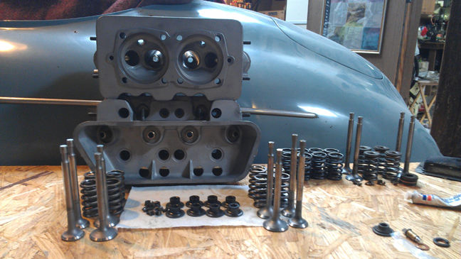
Previously, we went through a large batch of about 40 new springs and they were grouped by strength. We match up slightly stiffer springs with the heavier valves (intakes are about 2% heavier than exhausts), so they're very close sets, matched up, so all the valves tend to float at the same time. ...Of course, each valve and retainer are position-specific through the shimming process...
OK, time now to do a little more on the crankcase...
Finally an engine stand opened up - OK, it's a test stand (note starter mount) and you can't assemble the crankcase on this stand! However, it's fine for finishing off an engine. Again, here you can see, if you look very closely, the rubber o-ring mounted on the end of the oil pickup tube, like later cases had stock, as discussed previously.
Very quickly, the timing cover was mounted... Note that it's a large oil pump engine.
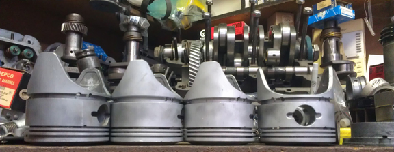
Time to install the Pistons and Cylinders.
Super pistons selected:
Super pistons can be positively identified by the fact that all normal pistons have a flat crown and all Super pistons are not flat. The bore is 82.5, of course, and these are long-skirt style as it's a plain-bearing, non-counterweighted crankshaft. These have three 2mm compression rings and one 5mm oil control ring. Oh, of course, we allways match pistons to cylinders and match piston weights as a set before installation.
Jumping ahead a little...
Here it is as a longblock, minutes away from being ready for pickup or delivery:
Yes, the distributor drive shaft was not yet installed when this picture was taken...
When you're ready for work on your machine, just let us know.
Because some people are keeping logs of VIN and engine numbers and then purport to tell people what someone else has, out of respect and concern for a buyer's privacy, exact VIN and engine number data are not published here.