Copyright © 2007 - 2024
Copyright © 2007 - 2024, Coachworks For contact data Click
Here. ![]()
This engine has been sold but this page has been retained for reference purposes.
 Porsche
Engine
Porsche
Engine
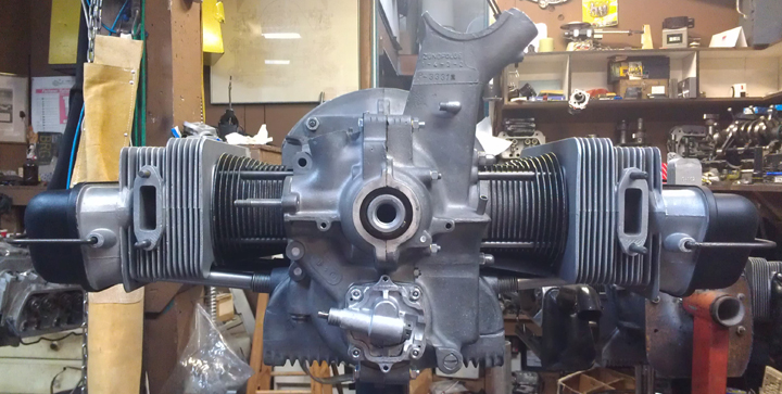
This engine, in long-block form, is ready for pickup or delivery now.
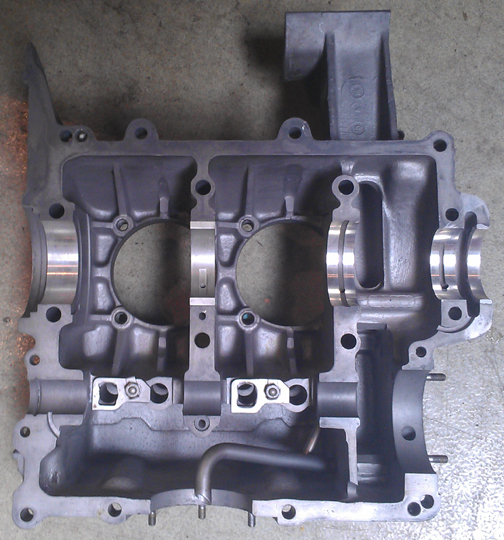
This 1954 Porsche 356 1500cc type 546 engine is completely stock and correct, has new pistons and cylinders and has just undergone a complete overhaul, and is fully balanced for smooth running, long life, and a few more HP.
 The
crankcase is "numbers matching" and is in very good condition. The
crankshaft has been upgraded to Porsche 356 B due to the improved strength.
It is fitted with cylinders which replace the original chrome with more durable
iron, and reproduction pistons. The camshaft is also a correct 546 104, (1500N)
- very rare indeed.
The
crankcase is "numbers matching" and is in very good condition. The
crankshaft has been upgraded to Porsche 356 B due to the improved strength.
It is fitted with cylinders which replace the original chrome with more durable
iron, and reproduction pistons. The camshaft is also a correct 546 104, (1500N)
- very rare indeed.
Every detail about the engine has been attended to, as outlined below; nothing was overlooked.
As with many others, I obtained this engine decades ago and, like some of the more interesting ones, kept it on an indoor engine shelf where it has sat until recently. The earlier history is completely unknown, but many people have seen this engine sitting on the engine shelf in the workshop, so you could perhaps jokingly call it a "well known engine!" But regarding its specific history, I do recall that I obtained this engine shortly after I got a '54 356 1500S Coupe, and was looking to ensure I had all the pieces I needed for that vehicle. By chance, I attended a PCA organized gathering and happened to be asked to introduce myself and indicate what special interests I may have. So, I included a comment about the '54, and someone in the group came forward to indicate they had a 1500 "Damen" engine in their garage somewhere on the San Francisco Peninsula.
Information was exchanged, I followed up, and picked up the engine shortly thereafter. While receiving the engine, the seller indicated that they'd had an interest in the cars, found the engine as a starting point, but somehow gave up interest. They said who they got the engine from, that the engine's original vehicle was unknown to them, and unknown to the person they got the engine from. They'd never owned a correct car and had lost interest in securing one, and they figured that since I had a correct automobile, that was closer to an appropriate home than what they provided. So, they offered it to me. They did, however, demand full value for the engine, stating that they were only asking what they had paid. It was "shocking." I recall several people advising me it was way too much money, but as they didn't have another one on offer, I thoughtfully ignored them.
The first thing I did was put it on my engine shelf and ignore it while I continued to acquire bits for my '54. Eventually, I turned my earnest attention to my '54 and collected up all the things it needed. A few bits came off this engine, but that's exactly what I bought it for! What remained untouched was a long-block - and there are a few bits left over (like intake manifolds) as trading stock. And so it's the remaining long-block that is now being rebuilt and offered to you. I don't know anything further about it regarding its history.
When I finally tore this engine down, it was remarkably dirty. I was a bit annoyed about that! However, things were otherwise mostly unremarkable about it.
Mostly, when we think of remarkable things about engines we tear apart, these remarkable things are the things that are wrong or are problems! On rare occasion, we are delighted with what's good or perfect, too. As I look back on this one, the only notables were that the pistons and cylinders were 1600cc sized, and that the whole thing was so filthy, it stands out as dirtier than usual as I already said. As is extraordinarily common, there were plenty of assembly errors from a previous reassembly, but that's not really remarkable - it's the norm!
Curiously, the pistons were SC / 912. They had shimmed the cylinder bases so far out to avoid the pistons hitting the heads that they lost any benefit there was to the improved CR! At least they knew enough to shim the cylinders far enough out to avoid disaster. Unfortunately, their home-made shims are of no use in building future engines - apparently, cylinder shims of this size were as rare then as they are now!
The reason to rebuild this now was that while I don't have any particular application for it, I just finally decided that I wasn't getting any younger and I ought rebuild it.
The first thing to do was prepare the crankcase. OH what a CHORE! I cleaned two at once, this engine, and another Damen, 3203x (see this link for more on that one), and they both were extraordinarily challenging to clean.
 I
should have cleaned them up YEARS before, back when we could get real solvents.
The parts washers of today just plain don't work in comparison to the old stuff.
DAYS were spent soaking! MORE than 12 hours were spent scrubbing with a modern
"hot" water-based "solvent" parts washer, just trying to
get the crankcase clean! Eventually I got it clean enough to media-blast and
then removed and replaced all the "soft plugs" that plug the various
oil drillings - this was done to ensure that ALL the media was removed!
I
should have cleaned them up YEARS before, back when we could get real solvents.
The parts washers of today just plain don't work in comparison to the old stuff.
DAYS were spent soaking! MORE than 12 hours were spent scrubbing with a modern
"hot" water-based "solvent" parts washer, just trying to
get the crankcase clean! Eventually I got it clean enough to media-blast and
then removed and replaced all the "soft plugs" that plug the various
oil drillings - this was done to ensure that ALL the media was removed!
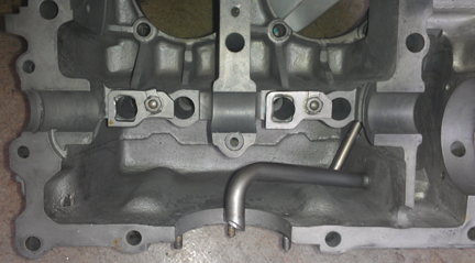
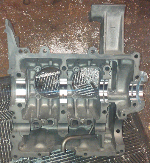
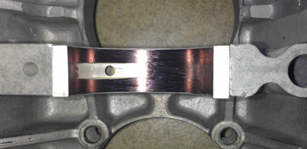
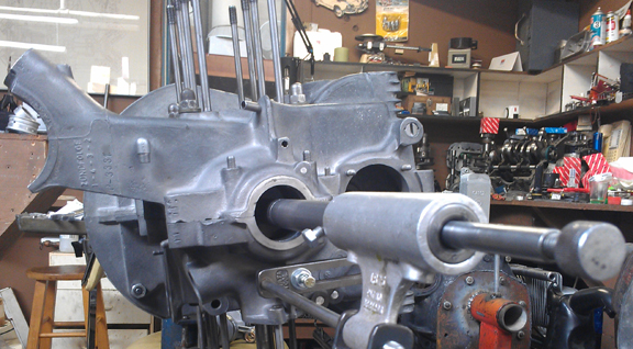
Unfortunately, I didn't think to take any "before" photos showing what the case looked like prior to cleaning - if I'd had any clue that it would be this difficult, I would have because it would be very enlightening to see just how long it takes to clean up a mess! If it weren't a rare, two-piece crankcase, I don't think I'd have bothered! However, the image at right shows the hardest area to clean - the casting parting-line that runs horizontally in the sump area. Note how clean it is now!
Curiously, both this engine and it's "sister engine" crankcase's crankshaft bores were worn almost exactly the same. Bores 1 through 3 averaged about 60.15 mm, with some spots up to 60.2, just as with the other Damen I cleaned at the same time. This size is quite a bit too large but does indicate the case had never been "align bored" before. (Standard on a two-piece crankcase is nominally 60mm). OK, re-bore the crankshaft bore to the next size larger.
 Oops!
Oops!
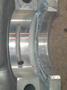
ANOTHER fluke! Just as with the other Damen, the bore for the pulley (where the oil-return threads go) was too large! This is vital for two reasons: 1) if too large, oil can escape between the pulley and crankcase and the engine "weeps" oil (or worse), and: 2) for align-boring purposes, the pulley bore supports the boring bar (that in turn supports the align-boring cutters) and provides alignment to center on one end (the flywheel seal's recess providing that service on the opposite end). This engine's pully bore was not as huge as the other Damen, but it was too large to support the boring bar and likely would have leaked there.
Rather than clutter this web page up with what has become for me a "routine process" (I've done about a half-dozen so far), I'll merely point you to this page I wrote to describe the process, and maybe help others who may encounter the same problem. Also on that web page you will find, near the bottom, an image or two showing the boring process in action - this is the same exact process used to "align-bore" the crankshaft bore in crankcases, just with the boring bar supports further outboard.
However, at right you can see the completed work on this engine's right half. Yes, new material was welded in and then machined to proper size...
 With
the pulley bore back to standard, it was time to bore the crankcase itself.
I gave it a try at 60.25mm (standard for the later engines) and would then use
three piece crankcase bearings, but the bore didn't clean up. That's to be expected
when some of the bore is already at 60.2mm. So, it went to 60.5, which is considered
the "first oversize" anyway. At right you can see the freshly bored
crankcase at 60.5mm (nominal).
With
the pulley bore back to standard, it was time to bore the crankcase itself.
I gave it a try at 60.25mm (standard for the later engines) and would then use
three piece crankcase bearings, but the bore didn't clean up. That's to be expected
when some of the bore is already at 60.2mm. So, it went to 60.5, which is considered
the "first oversize" anyway. At right you can see the freshly bored
crankcase at 60.5mm (nominal).
There are more checks to be made... Thankfully, the oil pickup tube is very tight in the case. (It can be challenging to repair a loose pickup tube.) And, all the threads are fine, including the rear-most two, that accept the forward pulley shroud. These are often stripped. Out of habit, I ran a tap through the pulley shroud's screw holes and cut a few more threads just to ensure there's no problem later. (Long M6 bolts should be used here - which is good advice anyway.) And, unusually, all of the sump studs are fine and needed no repair (image way below).
In the image at right, one of the lifter alignment plates is lose and dangling. This engine had clearly been reassembled - on the most recent previous occasion it was reassembled, I believe - with ill-fitting lifter alignment plates. Later on, when we get to "crankcase assembly," I'll rectify this by replacing some and properly adjusting all of these alignment plates.
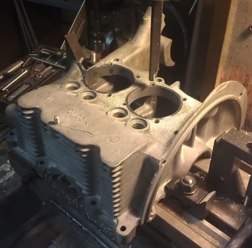
Not forgotten, the cylinder "decks" were checked that they are in one plane with their immediate neighbor using a special tool designed just for this purpose. This check reveals whether the cylinder spigots - the metal surrounding where the cylinders meet the case - are at the same relative height to each other. In my experience, the middle area between the two cylinders is nearly always too low on these older two-piece crankcase engines. On this engine, the left pair (3 and four) were OK, but the right side was at the specification limit (0.1mm). So, that half was mounted to the mill table and the spigots refaced in a process sometimes referred to as "decking the cylinders". This process ensures that both cylinder bases on that side are truly in the same three-dimensional plane. You can see that happening below:
Following this, the crankcase was thoroughly cleaned and then I replated the crankcase, as was originally done, with the Dow 19 process. This process sometimes creates a brownish gold coloration, but in this instance, it just made the crankcase a more consistent grey. The real benefit is that it helps protect the magnesium, wich is very galvanically active.
 As
cited above the crankshaft fitted is a "B" type because it happens
that the early crankshafts were more prone to breaking than the younger cranks
are. And, the original crankshaft - or, at least the one that came to me! -
was already reground to "30 / 30", which means that bearings are very
hard to come by, and the crankshaft itself is on "it's last leg",
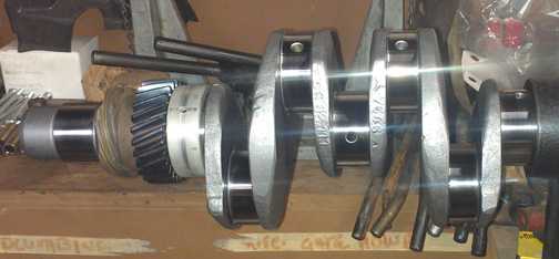
so to speak. So, I sourced a "10 / 10" B crankshaft and had it reground
as necessary. It is now at "20 / 20" on its rods and mains (nominally
49.5mm, and 52.5, respectively). As a first step, I had it magnifluxed to
check for cracks and then, after grinding, it was thoroughly cleaned and polished
- it just gleams, as you can see at right.
As
cited above the crankshaft fitted is a "B" type because it happens
that the early crankshafts were more prone to breaking than the younger cranks
are. And, the original crankshaft - or, at least the one that came to me! -
was already reground to "30 / 30", which means that bearings are very
hard to come by, and the crankshaft itself is on "it's last leg",
so to speak. So, I sourced a "10 / 10" B crankshaft and had it reground
as necessary. It is now at "20 / 20" on its rods and mains (nominally
49.5mm, and 52.5, respectively). As a first step, I had it magnifluxed to
check for cracks and then, after grinding, it was thoroughly cleaned and polished
- it just gleams, as you can see at right.
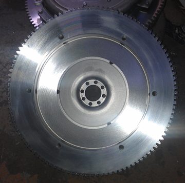
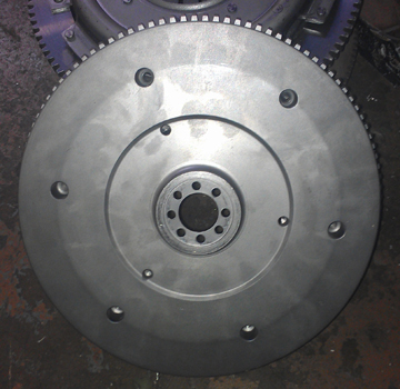
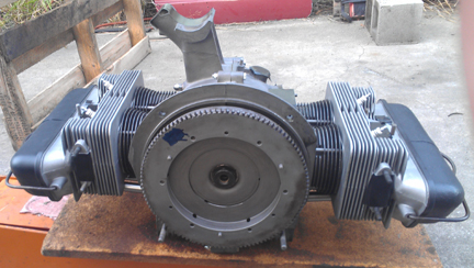
The flywheel seemed fine, has a lot of life left in it, and the starter teeth are in good condition, so I had a friend of mine who has the right machine tools resurface the clutch face and then rotationally balance it.
 Because
at this point the main bearing sizes are known, I sourced a bearing set, then
mounted the thrust bearing on the crankshaft and went through the iterative
process of mounting and dismounting the flywheel to try different shims to set
the end-play. While it can be done later, this work is always better done by
using a feeler-gauge before the engine is assembled.
Because
at this point the main bearing sizes are known, I sourced a bearing set, then
mounted the thrust bearing on the crankshaft and went through the iterative
process of mounting and dismounting the flywheel to try different shims to set
the end-play. While it can be done later, this work is always better done by
using a feeler-gauge before the engine is assembled.
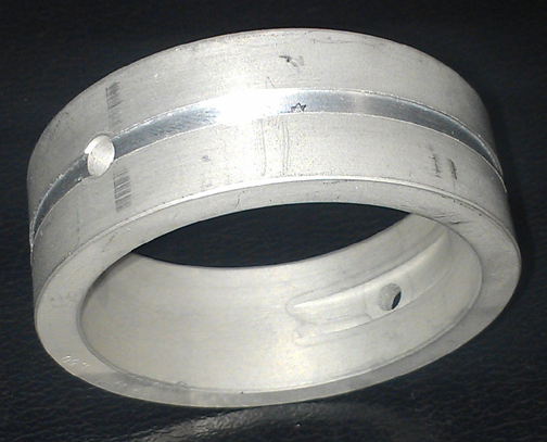
One must speculate why VW and Porsche both had only one official "oversize" on the main bearings, 60.5mm (nominally) during the "two piece crankcase" era. They later chose 60.25 as standard for the three piece crankcase, and indeed many of the earlier crankcases won't "clean up" at that diameter, so maybe it was just a practical matter of saving a fruitless boring exercise (as I myself usually do anyway, since we can get the 60.25 bearings these days - might as well try!) But that doesn't explain the lack of a 60.75mm bore, as was available with later crankcases. One day I realized the answer: The early crankcase provides oil to bearing number three through a concentric groove in the crankcase; if you bore larger than 60.5mm, this groove goes away and thus, there's no oil passage available! They probably figured it wasn't worth retooling to make it deeper. However, on later main bearings, they provide a groove in the bearing to do the same job. So, now I take a moment to "dress" bearing three to provide the missing volume of the groove in the bearing itself. Here you can see that process completed on this engine's main number 3. It's not a deep groove as I only removed about the same material as was removed from the crankcase during the align-bore process so the original pressure and volume of oil is maintained.
Note in the image at right the skuff mark just right of the left oiling hole - this is from pushing the bearing into the crankcase half to check fit.
Next, after trial-fitting the bearings in the crankcase (there's an image of this below), bearing three, the two gears that go on the crankshaft, their spacer, and the lock ring were installed onto the crankshaft.
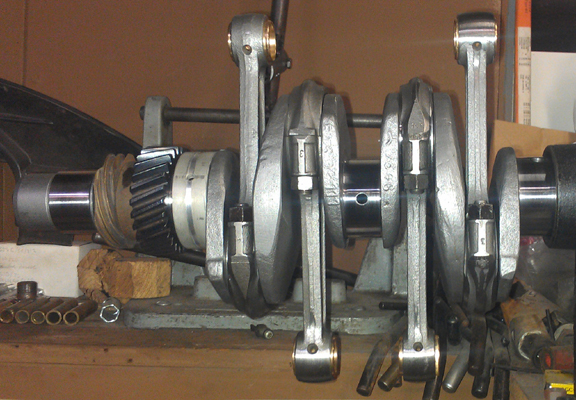
 I
then pulled out a set of already rebuilt rods, mounted the crank in the crankshaft
stand and installed the rods.
I
then pulled out a set of already rebuilt rods, mounted the crank in the crankshaft
stand and installed the rods.
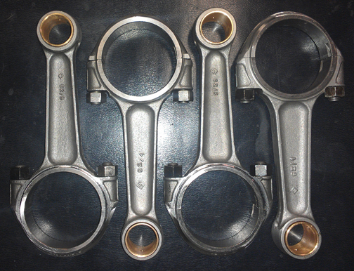
For me, "rebuilding the rods" means to:
This is all standard work so there aren't any photos of them in-process. However, here they are when assembled onto the crankshaft:
 Crankcase
Assembly
Crankcase
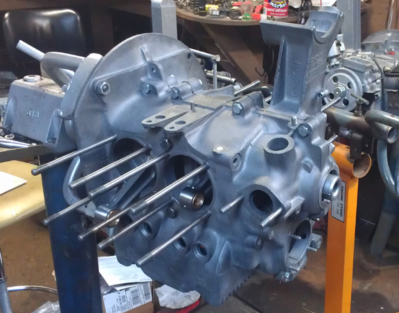
AssemblyAt right, the right case half, ready for assembly. The studs were removed during the case preparation phase for decking of the cylinders on this side.
Again, you can see how clean the crankcase is - I'm proud of that because it took so much work!
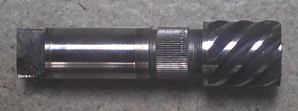
I got some new 1500 N camshafts, 546 104, from Richie Lukes's friend Dema (who is now my friend too). Here you can see the end of the one that went in this engine:
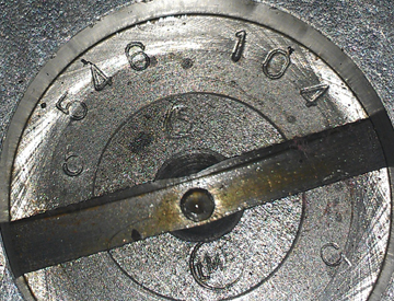
Note how the oil pump drive slot is perfect ... because it's new! And yes, that's a Sachs logo above the drive slot, and the LMB logo below. LMB is most notable for making 356 crankshaft pulleys. Sachs, meanwhile, is famous for cams and clutches, among many other parts.
To go with the new camshaft, the lifters were refaced:
In laying in the crankshaft, for trial fit of the camshaft, we found trouble! The crankshaft wouldn't turn! The dowel pins were correctly seated, the bearings perfectly in place, it just wouldn't turn, and that's just literally laying it into the open left half! Serious investigation was necessary. It's not all that uncommon that you have to torque the case together before a crank will turn freely, but the cam gear has to be selected with the case open. Indeed, fully torqing the case halves together did permit the crankshaft to rotate by hand, though not as freely as it should. I'm sure most people would have ignored it and moved on, but I insist on building a better engine.
It was easy to determine what was wrong. In removing the middle main bearing (the split bearing, #2) , everything was perfect, so bearing #2 gets the attention! Measuring the bore of the bearing, installed, as well as the bore of the case showed that there was in theory a sufficient clearance for the crankshaft, the problem was that it wasn't concentric. That's not supposed to happen when a crankcase gets align-bored! There are no tool errors that can create this circumstance. Rather, as I learned in talking with my old-timer friends, it turns out that while it's not supposed to matter what order the case half cap-nuts are torqued, in some instances, it actually does. But, as I hadn't used any particular pattern when I torqued the case for align-boring, I couldn't repeat it!
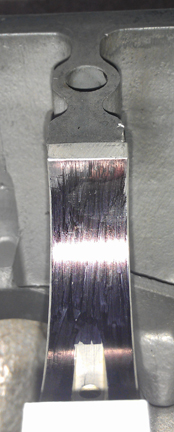
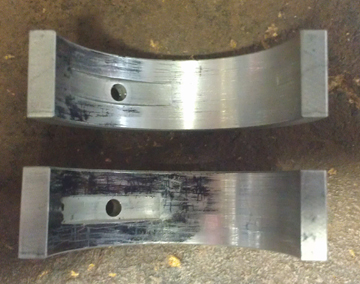
To prove this was the problem, I laid ink on the middle-main bearings - I would have used dykem, but I was out (got spilled), so I just used a black marking pen to lay down a bit of ink. I then installed the crankshaft with the middle mains inked but dry and torqued the case. Turning the crankshaft then marked the ink, as you can see in these images.
The upper image of the left two below is a bearing inked, below that is one half showing where the crankshaft rubbed (left side of image), and at right is the other half, showing a different wear point (at the parting line in the top left corner of the bearing):
What to do about it?
There were several choices. Old-timers would say, re-bore the case to the next size - that's what they'd do back when. I don't like that for two reasons: it takes metal out of the case, and finding the bearings is nearly impossible. Another solution is to get the next size smaller on the crankshaft - and I did find those bearings - and then bore them! Yet, there is another way... the problem can be fixed!
I sourced another pair of middle mains - lucky to get them! And, luckily, they are old-school Repco brand and (as I confirmed later) a bit thick - by 0.03 mm - and YES this matters!
While waiting on bearings to arrive, with the middle-main bearing removed, I fitted a camshaft gear. It's a minus 1.
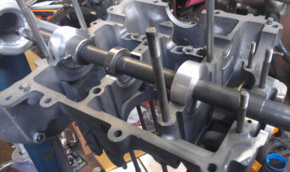
When the bearings came, I then made up some very precisely made supports for my boring bar and then bored the middle main bearing! No, I'm not saying I bored the bearing bore in the case, but rather the removeable bearing itself! Here you can see that happening - first, the boring bar layout. I did a trial bore on the first, inked set to test the cutter - you can see the inked set installed here:
Next, after boring that pair, measuring, and finding it useable, within specification, but a little looser on the oil clearance than I like, I installed the old Repco bearings and bored them. Here (below) you see the cutter lining up - note also the tiny bit of shavings from boring the first pair! - to wit:
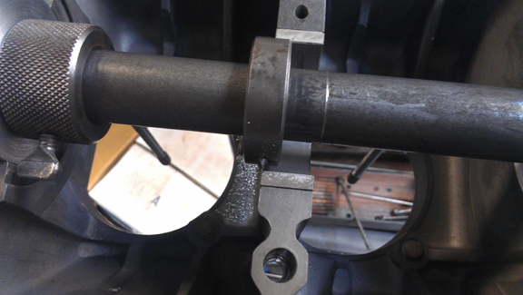
And, for the curious on how the rest of this works, here's a shot of the bar feeder mechanism (below) - when the boring bar turns, this unit moves the cutter a tiny amount along the axis:
As soon as the boring of each pair was done, I torqued up the case and measured the result. Depending on which bearings are used as input to, this process doesn't cut a perfect circle because it only trues up the theoretical bore of the crankshaft, with oil clearance, and therefore doesn't cut a full circle of material out of the bearing if that bearing isn't the next step undersized. In any event, in this instance, the measured final oil clearance of the Repco pair was 0.068 to 0.078 - perfect!
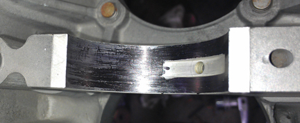
I was so delighted with how it worked out, I immediately proceeded with cleaning and assembly, using the bearings just fabricated, and didn't think to take a photo of them - the Repco bearings... However, here is the first pair, the "inked set". Note how the freshly cut surface blends in with a smooth transition to the un-cut areas (which retain the ink) - this set, imaged below, is not the over-sized set. Run your fingers across them and they're absolutely smooth - no "step" or edge. (Note that some ink was lost by the bore measurement gauge making contact as the ink has not "soaked in" and is easily removed by rubbing.)
(Note that the above bearings will be provided as spares - I have no use for them!)
Here's the short-block that emerged a few minutes later:
I then mounted the oil pump housing, oil sump screen, and oil control piston. Oh, this image of the sump studs belongs somewhere - they're in great condition:
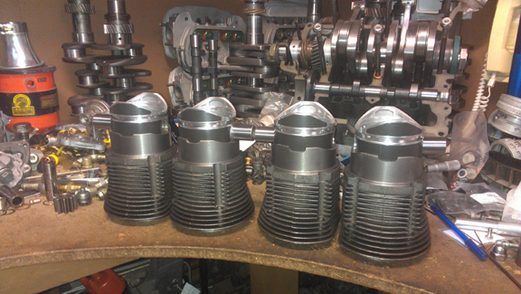
Time to install the Pistons and Cylinders.
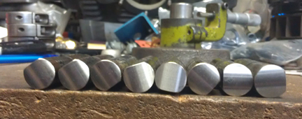
A reproduction set of pistons and cylinders is presently available for the two-piece crankcase 1500cc "normal" and I was thoughtful enough to buy a set instead of using used ones. Here they are, rings removed:
 I've
used several by now, one older (from the same vendor), and the newer ones have
slight changes in the cylinder from the older production. On the set for this
engine, the newer production, I found the OD on the cylinder head end a few
thousandths large, but this was easily trimmed in the lathe.
I've
used several by now, one older (from the same vendor), and the newer ones have
slight changes in the cylinder from the older production. On the set for this
engine, the newer production, I found the OD on the cylinder head end a few
thousandths large, but this was easily trimmed in the lathe.
In my view, piston weights need to match very closely in any single set, and I strive for 0.1 gram, while the stock specification for early engines is something like 16 grams, if I recall correctly. Whatever the exact spec., it's large, and I never assemble an engine that out-of-balance.
These pistons have three 2mm compression rings and one 5mm oil control ring, and appear to be exactly stock.
These are semetrical, non-offset pin, cast pistons - as original. The quality of the castings appears to be quite good.
 When
it comes to the cylinders, including fitting pistons to them, here's our process:
Two of these steps require special tools most shops don't have.
When
it comes to the cylinders, including fitting pistons to them, here's our process:
Two of these steps require special tools most shops don't have.
 I
like to carefully measure everything and then mix-and-match the parts for superior
fit. For example, the pistons are washed, and weighed bare, the pins weighed,
and then pins and pistons are re-matched for a better balance.
I
like to carefully measure everything and then mix-and-match the parts for superior
fit. For example, the pistons are washed, and weighed bare, the pins weighed,
and then pins and pistons are re-matched for a better balance.
In carefully matching up the parts, I have regularly found significant manufacturing errors with this process which would likely have gone unnoticed without these measures. It is remarkably easy, for example, to overlook the circumstance of the crankshaft bore not in the true center of the crankcase, angled on the horizontal left or right of center, or not on the same horizontal plane at all. Sometimes the pistons don't all have the same pin height (distance from pin center to crown). Examples of errors like these are not as uncommon as we would like. The key then is "did you even notice?!", and, if so, "what do you do about it?"
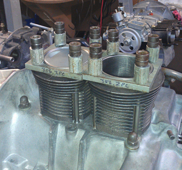
Here you can see (above right, and directly right) cylinders being fitted for height comparison check - this is done to ensure that there are no difference between the cylinder heights that the head itself "sees." The book value for tolerated error is 0.1mm (four thousandths of an inch), but in this case, there was no measurable difference between one pair, and about 0.002" (two thousandths of an inch, or 0.05 mm) for the other.
Note that as a part of this work, one fits the cylinders to the case looking for interference with the cap nuts or through bolts. Invariably, no matter who made the cylinders (almost without exception), there's an interference somewhere. Generally, the cylinder is ground slightly to provide clearance, but some engine builders grind the cap nut or bolt head. These cylinders hve a nice thick bottom rim which is easier to control for such grinding than some cylinders out there, like the NPRs, which usually strike on the lowest fin.
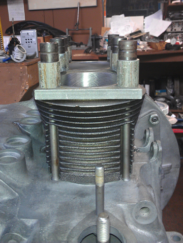
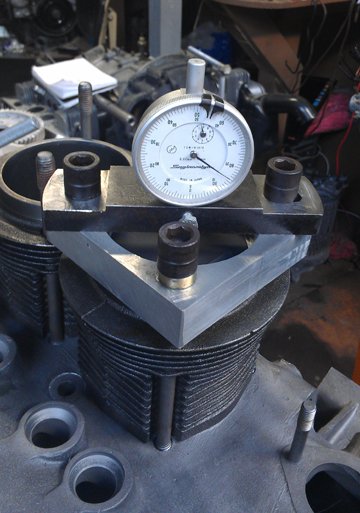
The next thing we do is something nobody else does (that we know of) in the engine building process, and that is to measure the height the piston crown comes above the plane of the top of the cylinder. I call this the CAC, or "Crown Above Cylinder." This value is important because, firstly, it can reveal deeper problems, and because it helps us get the compression ratio equal in all four cylinders.
 Here
are some of the deeper problems that can be discovered through a CAC check:
Here
are some of the deeper problems that can be discovered through a CAC check:
In order to do this for these engines, you have to have special tools. Here, you can see them in action at right.
If you can't read the dial face in the image at right, the distance between the smallest tick marks is one hundredth of a mm, or 0.0004", and you can discern to perhaps a tenth of that! So, this is a very accurate measure, performed while the cylinder is under torque, so any shims are squished flat, etc.
The accuracy is so good, that if you take the time to swap parts around, you can accurately determine discrepancies in the manufacture of the various parts! But, we ARE splitting hairs here! However, a benefit to both engine builder and customer is that the ability to move parts around for better fit means that perfection is more easily achieved, and the more equal the HP production of each cylinder, the smoother the engine will run, and the more HP the engine will produce overall.
Because this process includes the entire assembly, torqued as in service, and measures the height each piston protrudes out of its cylinder, all errors in connecting rod lengths, cylinder heights, crankcase spigots depths (cylinder bore deck), piston connecting pin heights, and shim thickness' are accounted for in the measurement results. There is no superior method.
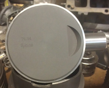
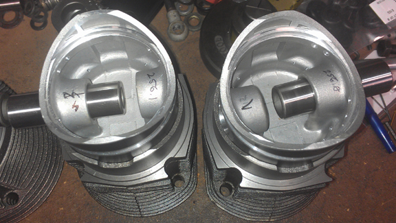
Here are two of the pistons, bare, cleaned, weighed, matched up with pins and then assigned an installation position:
 Once
this work is done, one needs the heads to be ready to confirm combustion chamber
sizes in both heads, do any shimming, then mount the rings and install the pistons
and cylinders.
Once
this work is done, one needs the heads to be ready to confirm combustion chamber
sizes in both heads, do any shimming, then mount the rings and install the pistons
and cylinders.
As a result of this measurement work, it was determined that even when all the pistons were arranged to best advantage, three cylinders' compression ratios were within one tenth of a point - that's FANTASTICALLY accurate! - while one odd-man-out was about three tenths of a point higher! The data reveals that the primary problem was that one piston's pin height (pin center to crown) was bored incorrectly by about 0.3 mm, and a secondary problem was a slightly small combustion chamber on that one cylinder. Because the cylinder heights matched, there's no shimming out of this, but there are options.
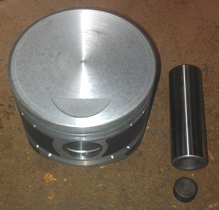
You could grind the valve seats deeper, moving the valves outboard making the chamber larger, you could enlarge the combustion chamber with a die-grinder - neither of which are very easy to get the right amount of material out (and it's time consuming to take repeated measurements), or you could take it off of the piston, which is, relatively speaking, very precise because it's taking material off "a solid circle", the volume of which, per given depth, is known, and it's quick and easy since it's done in a precision machine. Since most of the problem was caused by the piston's manufacturing error in the first place, that seemed the obvious way to go, so 0.3mm was taken off the crown to make up for the error in manufacture, and an additional 0.2 mm was taken off to make up for the difference in the cylinder head. (This has the additional advantage that the P&Cs are the most easily replaceable part in the engine, and are often replaced at rebuild time anyway.)
Of course, this throws off the weight of the piston, which is now much lighter than it's partners. When I say "much", it was STILL within the original specifications, which, as indicated before, are unacceptibly large from today's viewpoint. As it would be difficult to take enough material off of all three other pistons, and as there are no connecting pins heavy enough to make up the difference, I'm sure many engine builders would shrug it off and say, well, it's within spec! However, I don't built engines that are simply within specification! So, a slug of steel was made up to have an outside diameter just a tiny bit larger than the inside of the connecting pin, that slug was then ground down to a precise weight, and then it was drifted into the inside of the connecting pin. Thus, the piston / pin assembly is back to matching all the others - still within 0.1g. Perfect! (See the trimmed piston, its pin, and the "slug" above right.)
Now the engine is ready for the pistons and cylinders to be installed, followed by the cylinder heads.
 Cylinder
Heads
Cylinder
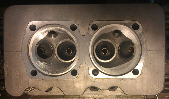
HeadsThese heads were from this engine originally, best as I can tell, and they're a mated pair. Unfortunately none of the "before" photos I took turned out - too dark and fuzzy. Note that there are zero differences in the castings, they both have the identical combustion chamber sizes, and they were ported to match, also.
The heads had all original bronze seats in them. Richie said that they liked them because they seal more reliably than steel seats, at the expense of longevity. Well, we want longevity now, and we have better materials than they did then, so installing new steel seets seemed the thing to do. And, of course, new guides.
They're nice heads, but not perfect. The biggest flaw was that something got loose in one combustion chamber and beat up that combustion chamber a bit. This is probably why the engine was fitted with different replacement pistons as at least one of the originals didn't survive.
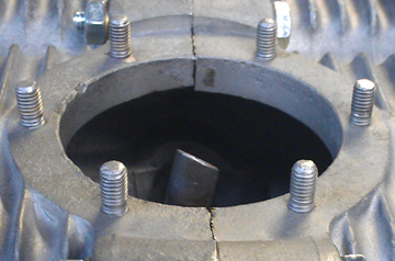
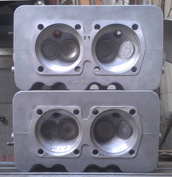 In
the image above right, you can see that head, the damaged combustion chamber
on left. Note that I made a "conical cut" in the combustion chamber
to remove most of the damage, in particular to ensure there are no hot-spots
that could in extreme conditions cause predetonation (pinging). The remaining
marks are just cosmetic.
In
the image above right, you can see that head, the damaged combustion chamber
on left. Note that I made a "conical cut" in the combustion chamber
to remove most of the damage, in particular to ensure there are no hot-spots
that could in extreme conditions cause predetonation (pinging). The remaining
marks are just cosmetic.
Of course, the other combustion chambers were cut identically so the cylinders will remain "balanced." The conical cut also makes the combustion chamber a little larger while the decking makes them smaller, so there's little net change in volume.
"Install new seats and guids" is very easily said, but very hard to do! The reason is that the specifications book lists three different setups, all with different installation dimensions, and none of the parts are readily available anyway. So, you have to carefully measure which of the three possible types is presently installed and then make the new parts to fit! That's right, the valve guides and seats had to be made for these purposes "from scratch." (Pretty useful stuff, that scratch!) Actually, we don't start with ore and don't have our own smelter, but rather source similar, appropriately sized parts and then modify them to fit correctly. You can see the new seats pretty clearly in the image above, while the guides are harder to see here, but are more easily seen in later images (below).
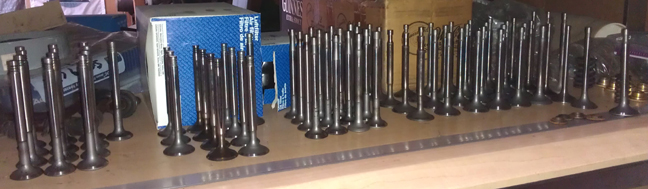
The valves themselves were all cleaned, refaced and polished. Some were likely replaced - I didn't pay attention to which valves came from which heads, I just processed another batch, like I usually do, then selected good ones for this project.
In these images you can see further work on the heads; the heads were both decked and fly-cut because to install seats, the heads have to be heated pretty high, but cannot be supported during this heating and they can warp slightly. Decking afterward ensures the cylinder seats are in the same plane. Then, the surface closest to the crankcase gets cut down to match however much was taken out in cleaning up the cylinder sealing surface, thus ensuring the heads don't foul on the cylinder's top fin.
 Also,
didn't think to show a closeup on these heads, but perhaps you can still see
in the first image of this section how well the new seats fit these heads -
they're perfectly centered, match in ID and height. I'm very pleased with the
work as sometimes there are small errors to clean up later with a die-grinder
- none of that needed here!
Also,
didn't think to show a closeup on these heads, but perhaps you can still see
in the first image of this section how well the new seats fit these heads -
they're perfectly centered, match in ID and height. I'm very pleased with the
work as sometimes there are small errors to clean up later with a die-grinder
- none of that needed here!
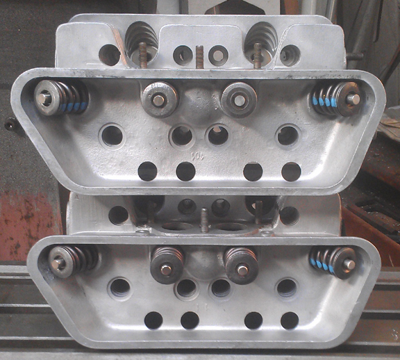
In these next images of the head (right and below), the valve seats are ground, and valves installed...
...And the combustion chamber volumes have been measured.
Note that there are some exhaust studs missing; the threads have already been checked, and I'll install new studs when the heads are mounted up as it's easier that way.
Also notice that there are no broken fins or other issues.
It was decided to use single springs instead of the original dual-springs. All original assemblies were dual-spring types, but Porsche later substituted a single-spring type, the so-called "third version", and provided the specifications for these in this specifications book. After quite a bit of hunting, I was fortunate enough to find springs that are a good match to the originals. As there are always production varriations in all mass produced parts, I always use these differences to match up slightly stiffer springs with the heavier valves (intakes are about 2% heavier than exhausts), so they're very close sets, matched up, so all the valves tend to float at the same time. ...Of course, each valve and retainer are position-specific through the shimming process...
Oh, the valves came from this stash, all checked for wear, refaced, and with the stems polished:
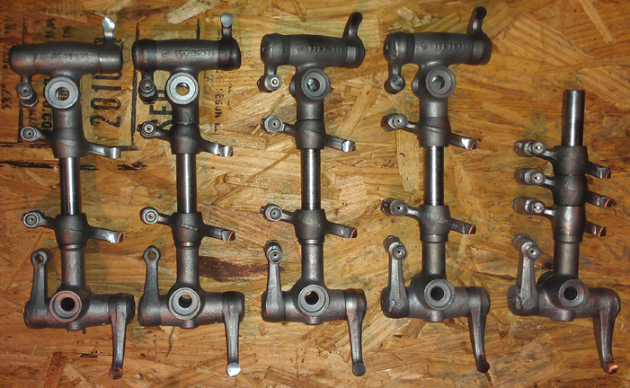
The rocker gear was all thoroughly cleaned and the contact surfaces refaced. I did two sets (plus) recently - this is one of those two sets:
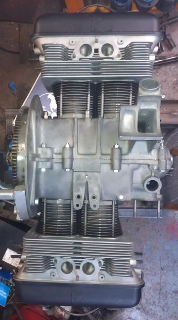
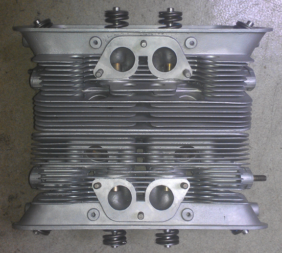
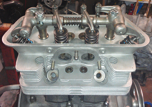
OK, bolt on those heads! Here are the results:
...During the rocker assembly process, most of the adjustment screws had to be replaced, and they consumed up the last of my NOS stock. All the adjustment screws are fantastic... As always, new adjustment nuts were fitted.
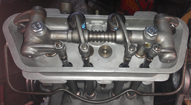
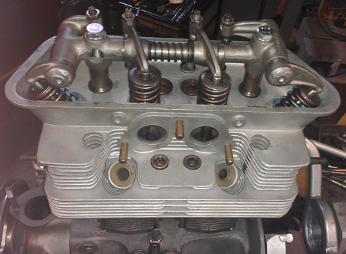
The other side, just as nice:
The gear on the oil pump drive shaft needed replacement, so I pressed it off, and found it was a very early shaft indeed - you don't see these splines on younger ones:
The new gear went on easily and is secure. ... Most oil pump drive shafts are smooth (no splines like this one), and a few very late ones (but not all) have a woodruf key securing the gear to the shaft. These splines are unique to the early pumps.
I then repaired the tang that fits into the camshaft by welding new material on to the worn places and then refacing it - this is a typical issue with the typical solution. The newly welded on material is harder than the original steel, so it should wear less. Oh yes, a new oil seal was installed on the tachometer drive shaft.
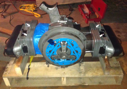
Here it is as a longblock, minutes away from being ready for pickup or delivery - just valve covers...
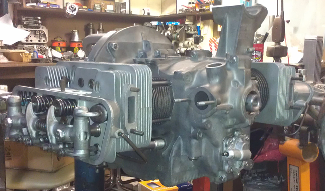
The distributor drive shaft has not been installed because it should be left out until a distributor will be installed. Otherwise, if anyone rotates the engine backwards, the drive gear will ride up on the bronze crankshaft gear and may damage it....
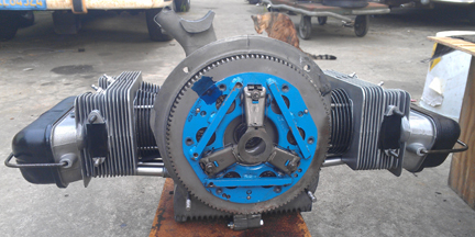
Well, off it goes to its new home. The new owner had me add a diaphram type, early throw-out style pressure plate - you'll see it in these images. And, I crated it for shipping, and off it has gone. In the following images, the crate construction is shown, which may be of some interest to folks.
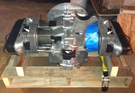
After dismounting from the engine stand, I torqued the flywheel a second time to ensure it's on good and tight. Then, I taped off all openings and brought the engine to the crating area using the over-size floor jack, whereupon I sprayed the engine liberally with WD-40 in preparation for its upcoming sea voyage.
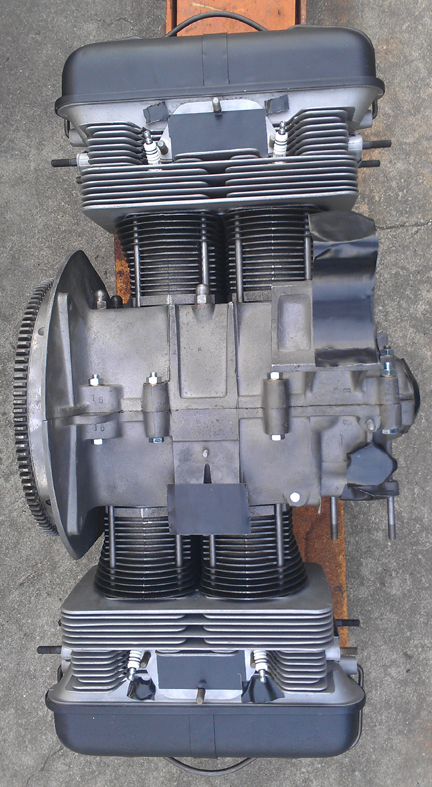
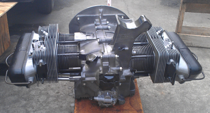
I then coated the pressure plate with WD-40 too, then set it in place.
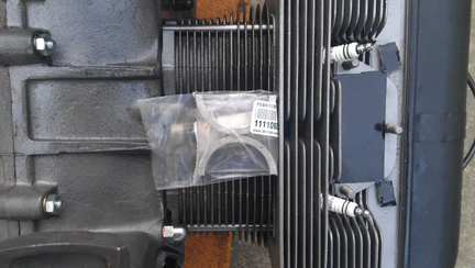
To ensure they weren't forgotten, I bagged up the distributor drive gear and its thrust washer, and the spare set of middle main bearings, and laid them between the cylinders on the right half, taping them in place. (Click here to see why the distributor drive gear wasn't already installed.)
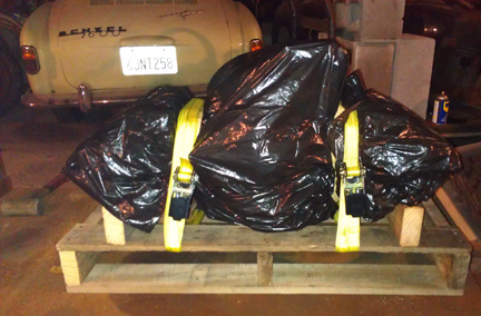
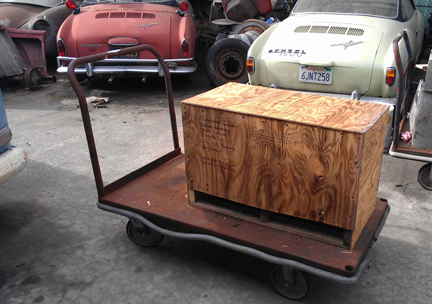
Meanwhile, off camera, I took a regular to large size palate and took off four rails and cut off some inches of the middle and end "2X4"s, and made a new, smaller palate that fits the footprint of this engine. Next, I set the palate on a cart, then set the engine on the palate, centered it, and braced under the heads to keep it from rocking. This adjustment was fine-tuned using wooden paint stir-sticks.
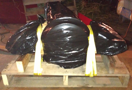
I then bagged the engine using two large plastic bags, taping the plastic down by looping masking tape around the cylinder areas.
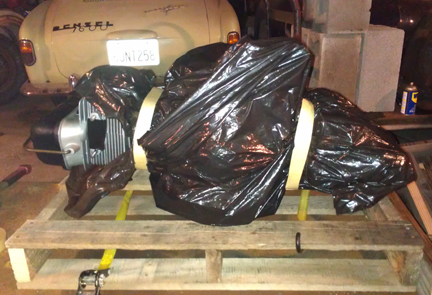
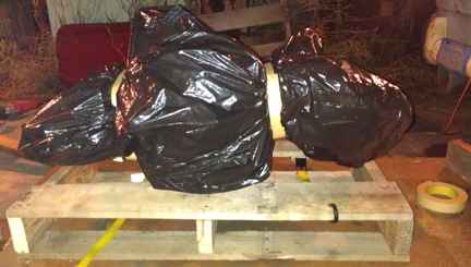
I then repositioned the head supports and then strapped the engine to the palate in a place where there's no way the strapping can slip off.
I then proceeded to build the crate around the engine, sides first, then the supports, then tied left to right, etc.
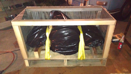
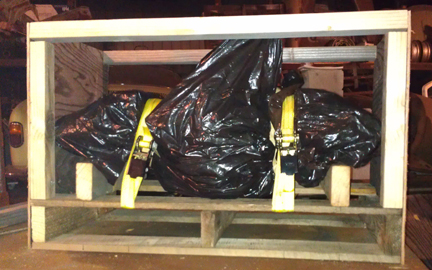
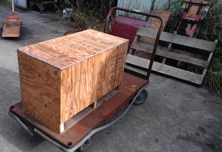
Not much later, we have a crate!
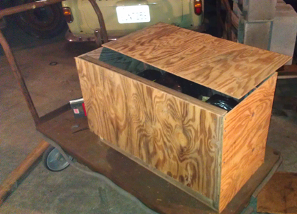
I then addressed it, put warning markings on it and it's ready.
I think it's a rather handsome thing - maybe I have another career as a carpenter ahead of me!
The shipper was rather prompt. As no forklift was available to help, the driver set out some ramps and I pushed the cart up onto this truck.
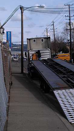
I helped a lot in positioning the engine up there, but thought it wise to let the trucker strap it in, so the liability all rests with one person on the next part of this engine's journey...
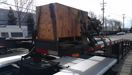
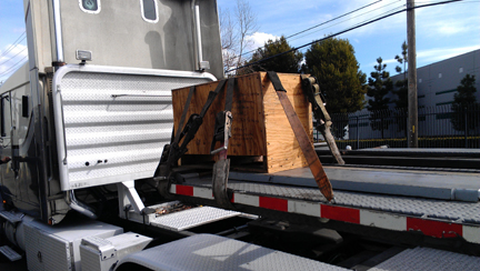
...And off it goes. I hope it lives a very long life indeed!...
NOTE: If this engine is sold as a long-block... One should NOT install the distributor drive gear without also installing a distributor because if anyone rotates the engine backwards, it will push the drive gear up where it can damage the bronze drive gear! Therefore, the distributor drive is NOT mounted until the last reasonable moment!
When you're ready for work on your machine, just let us know.
Because some people are keeping logs of VIN and engine numbers and then purport to tell people what someone else has, out of respect and concern for a buyer's privacy, exact VIN and engine number data are not published here.