Copyright © 2007 - 2024, Coachworks For contact data Click Here.
Copyright © 2007 - 2024
Copyright © 2007 - 2024,
Coachworks For contact data
Click Here.
![]()
 Un-Numbered
Two-Piece Case
Un-Numbered
Two-Piece Case
SPECIAL NOTICE
This web page is still under construction as is the engine!
A different, completed engine's web page was used as a template to create this page, and som materials are left-over from that other engine.
This disclaimer will be removed when all the images and text work has been completed.
While this case has "no numbers," the case casting dates are in 1953.
This case is presumed to be a 1500S because, while it has no numbers, it has two through-bolts - a feature thought (though not proven) to be unique to the 1500S series engines.
This engine is available already "run-in" as per Porsche factory specifications as outlined in the Workshop Manual, "Running-In and Testing" operations, 43 EN and 44 EN, pages E51 and E52.
Some people are concerned about roller bearing crankshafts and there is - or at least was - a reason for some concern. Namely, if the driver revs the engine up and "dumps the clutch" - like a teenager might do trying to spin the rear tires in a "burn-out", the rollers (or the races) can become deformed and cause catestrophic failure when metal particles begin to circulate in the oil, acting as an abrasive to wear out the rest of the engine. So long as you drive it like an adult, you're fine! But there's more to it - keep reading...
Also, back when these engines were first introduced, the oil pump had an 11mm gear and because the rod bearings are not sealed, the engine doesn't generally build up a lot of oil pressure, and this concerned people. Porsche increased the pump size to 24mm which provided over double the volume, and with it, a considerable increase in oil pressure. And, we have very much better oil today, so if you run a tall-gear pump, it's less of an issue today.
Additionally, there's a brand new oil pump that's just entering the market. It's got a 26mm gear - the tallest ever used, lots of volume, and it has passages in the pump cover that lets you take the oil out of the engine, "full-flow filter" it, optionally cool it, and put it back into the case all without modifying the crankcase at all. This way, if something does go wrong and the oil gets contaminated, the engine is protected from further loss by the particles in the oil being filtered out. Best of all, it retains the tachometer drive, so you don't have to sacrifice your original mechanical tachometer to the cause of improved longevity and insurance protection for your investment! There's a web page for the pump here.
Also keep in mind that the Carerras used a Hirth roller bearing crankshaft too!
This 356 type 528, 1500cc engine has just undergone a complete overhaul, and is fully balanced for smooth running, long life, and a few more HP.
The crankcase is "numbers matching" and is in very good condition. The crankshaft has been upgraded to the "B" series, which are less prone to cracking.
Every detail about the engine has been attended to, as outlined below; nothing was overlooked.
This particular engine came from a collection of four engines sold with a "1954" 1500S Coupe. It's clearly not the original for the car because it has no numbers and because the casting dates are a little early for it. The engine was already disassembled. The earlier history is completely unknown.
As indicated in the previous section, there's not a lot to say about the teardown.
 Crankcase
Preparation
Crankcase
PreparationThe first thing to do was prepare the crankcase.
It's too bad nobody cleaned it up years before, back when we could get real solvents. The parts washers of today just plain don't work in comparison to the old stuff. DAYS were spent soaking! MORE than 12 hours were spent scrubbing with a modern "hot" water-based "solvent" parts washer, just trying to get the crankcase clean! Eventually I got it clean enough to media-blast.
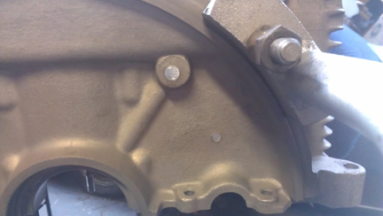
AT RIGHT: The right case half just prior to align-bore. Notice how clean the case is on the inside! No signs of corrosion, and a thorough check for craks revealed none. Nice!
During the inspection that followed, the cylinder "decks" were checked that they are in one plane with their immediate neighbor using a special tool designed just for this purpose. And, there's a reason for thorough checks like this; in this instance, both halves had a low-spot of between three and four thousandths of an inch in the area where the two cylinder spigots come close together. That is, the cylinders would be canted toward each other if nothing were done about it - and, of course, the cylinder head to cylinder seal would be stressed and could leak. This problem is pretty common on these earlier magnesium crankcases - much less so on the later aluminum cases. The solution is to "deck" the cylinder spigots, so the case is ready for long life, and while I was at it, I took a moment to also clean up the cylinder spigot bores because sometimes a bit of material gets shed into the crankcase interior during assembly if this is not done.
With the poor lighting at the mill, the photos I took of the decking process didn't turn out, but in later images, look for the bright rings around the cylinder spigots!
Following this, I re-plated the crankcase, as was originally done, with the Dow 19 process. This process generally creates a brownish gold coloration varying from just slightly golden brown to gray. The real benefit is that it helps protect the magnesium, which is very galvanically active. Note that the color shown in these images varies greatly depending on lighting.
The crankshaft bore was also checked and the case has never been "align bored". (Standard on a two-piece crankcase is nominally 60mm). BUT, unfortunately, some of the bearing bores were as large as 60.2mm, and wouldn't have held the bearings properly in the case. So, OK, re-bore the crankcase to the next size larger than 60.25, which on two-piece crankcase engines is 60.5mm (nominally).
 But
since you can't put the metal back very easily, just for the hell of it,
I gave it a try at 60.25mm (standard for the later engines) and then, if successful,
would use (slightly modified) three piece crankcase bearings because 60.25 is
not (and never has been, OE) available for two-piece crankcase engines. And
What Do You Know?! It worked! The bearing bores cleaned up at 60.25 just
fine! Here (at right) you can see the case about to be bored.
But
since you can't put the metal back very easily, just for the hell of it,
I gave it a try at 60.25mm (standard for the later engines) and then, if successful,
would use (slightly modified) three piece crankcase bearings because 60.25 is
not (and never has been, OE) available for two-piece crankcase engines. And
What Do You Know?! It worked! The bearing bores cleaned up at 60.25 just
fine! Here (at right) you can see the case about to be bored.
AT RIGHT: The crankcase torqued down, ready for align-boring.
But now I had a new problem: what main bearings! I have an extensive stash, so I dug out a set of "standard-20s", intended for the three piece case series engines, and prepared to make the nose bearing (#4). Before doing that, however, I asked my friends and got lucky that someone had an old stock "VW style" nose bearing in this size! It fit perfectly! (I'll leave it as an exercise for the reader to determine what the differences are between a 2pc and 3pc nose bearing!)
Following this, all the "soft plugs" were removed, permitting the internals of the case to be cleaned completely. (The factory provided "soft plugs" to plug holes that were drilled to provide the oil passages the engine requires.) There are several different sizes of soft plug and all were removed. So, of course, a full set of new ones was fabricated and installed. These pieces are basically slightly tapered chunks of aluminum that are very slightly bigger than each passage they close off. They are installed by driving them in.
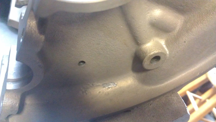
BELOW: Bores of two of the soft plugs (which have been removed) on the flywheel side of the left half, and; BELOW THAT new plugs have been installed.
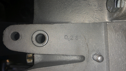
At this point, the crankcase underwent a "final check." Thankfully, the oil pickup tube is very tight in the case. (It can be challenging to repair a loose pickup tube.) And, all the threads are fine, including the rearmost two, that accept the forward pulley shroud. These are often stripped. Because the outermost thread or two are often not very sturdy due to the use of too-short fasteners and too much torque, I ran a tap through and cut a few more threads just to ensure there's no problem later. (Long M6 bolts should be used here - which is good advice anyway.) And, unusually, all of the sump studs are in great condition!
I chose to go all original. Some MANY years ago, I'd found a beautiful Hirth roller crankshaft with wonderful patina - looked brand new complete with original ink stamps, and it was clean. I foolishly sent it out to that crazy guy Jim Wellington who had purchased all the orignal tooling back when Porsche was done with it - he was reportedly struck by lightening more than once! He later reported that there was nothing wrong with the crank, it needed nothing, but he'd taken it apart to find out. And I had a hell of a time getting the crankshaft back from him. It literally took $1500 and around three years or more, but luckily he sent me a letter documenting the whole thing for me and my lawyer used it to write him a note basically saying, "thank you for giving us a slam-dunk court case against you, return the crank by this date or we're filing suit." That worked! Got the crank on the very day of the deadline!
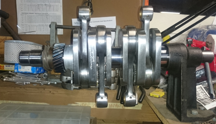
AT RIGHT: Here's the crank for some drying after the gears were installed. The crankshaft is put in a freezer and the gears on a stove, and the temperature differential lets them be installed easily, but the crankshaft will condense a lot of moisture as it warms up, hence the need to dry it. Note that the original patina is all gone, but Wellington signed the crank on the web between rods 2 and 4, as can be seen here.
Of course, the crankshaft needs the timing gears, so I selected new ones and a beautiful, and replated, oil slinger.
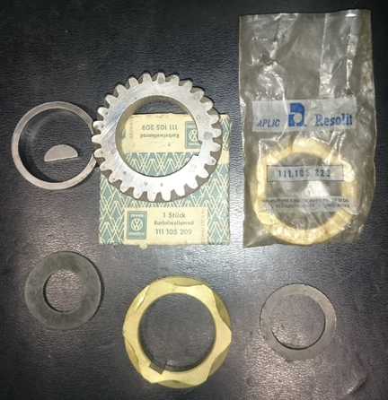
ABOVE LEFT & RIGHT: All the crankshaft-related parts are new - cam and distributor timing gears, spacer, gland nut and pulley lock washers and the pulley woodruf key. A new gland nut will also be fitted, and a replated pulley "nut."
As indicated above, I got a used but wonderful camshaft from Richie Lukes some 23 years ago or so. He provided not only the camshaft, but also the matched set of lifters that had been used on that cam, marked as to their original positions. They show no wear on their cam-contact faces. Richie asked me to be sure to keep them as a set and I have.
Here, I've just laid the cam in the left half to take a photo of it. I see now that the gear teeth need a little flossing! (Note also how spotless the crankcase is!)
Recall that the engine type for a '53 1500cc "normal" is 546. So, of course, that's what we see on the end of the cam... in confirmation of exactly what this cam is. And note too the perfect oil pump slot!
As you can see in these images, the camshaft and lifters are wonderful! The photography was rather difficult, though, because the parts are so shiny, it's hard to get an image that shows the face of the metal properly. One aspect of trying to get good images that I think is interesting is how with some of these images, my efforts to get a good clear image has resulted in magnification, so the images here are larger than the actual parts!
If you could see them in person, you'd definetly remark on how little wear there is. Note how there is absolutely no wear on that oil pump drive gear slot!
Below, you can see how the cam followers are in great condition, as described above. I'm guessing they really didn't see service as Richie had said - they just look like they've never seen a cam lobe since they were refaced (they're clearly not new).
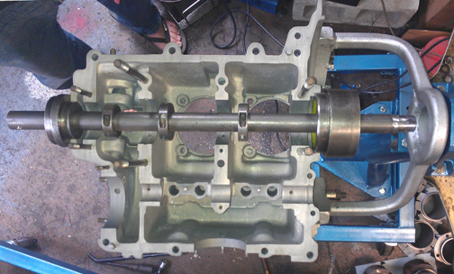
Crankcase preparation, described above, was a real chore. But assembly was a breeze! Here, the main bearings and cam are trial-fit.
All items are assembled into the left side (below):
At this point, the camshaft's mating to the crankshaft timing gear is evaluated. The cam gear selected is about as small as it gets, at minus two (-2), and it's worth pointing out two other things about it:
I don't usually take a photograph showing the case sealant applied, but, for a change, here's such an image - moments later, the right half was slid on and a short-block was created!
This seems like as good a moment as any to point out a few things visible in this image:
Just to be complete, here's the right half, sitting on a lidless box adjacent to the other half on the stand.
Yes, the reflection of light off of some areas makes it hard to see detail. There is some sealant around every main stud / bolt - the M10s that hold the halves together, and the two M8s at bearing four.
Also note that just before putting the two halves together, the excess, which tends to pool, is wiped away.
In all my 35 years or so building these engines, I've never yet clogged an oil passage, but I sure have seen others make that mistake! The application of sealant shown here is time-proven, and in my view, the text book example of how to do it right.
Here's the bottom bolted together, in the right image, still awaiting the parimeter bolts to be attached. Note the bright circles where the cylinders go as it shows the results of the decking operation described above.
Now the parimeter bolts - original black-zinc plated, with 14mm across-the-flats (atf), fitted with new clear-zinc plated 14mm atf nuts. You can see the bolt heads in the left half above, and the nuts in this image (below). (I would have used black zinc nuts but I ran out!)
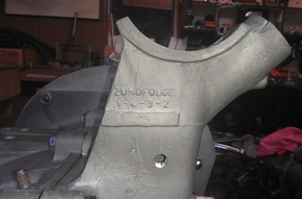
I provided this next image (at right) in this large size so you can read the cam numbers and the case number - with the last case digit illegible on purpose*.
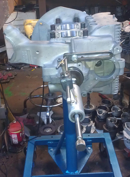
What we have here, at right, is called a "short block," even though we don't have "blocks" for our engines - they're crankcases!
Note the head studs are still out from machining the cylinder spigots - the shiny rings of which can be seen in the two images, right / left, immediately above this one.
Time to install the Pistons and Cylinders.
At this point, I had a decision to make as I had the following options:
After talking with a number of people, I settled on the new set - one piston and cylinder pair is imaged at right. (However, if you prefer an alternative choice, I can accommodate that for you - lets talk about that if that's what you want.)
In my view, while the stock specification for early engines is something like 16 grams, if I recall correctly, piston weights need to match very closely in any single set, and I strive for 0.1 gram. (I could check the spec., but it's hardly worth the time: I'm matching them far closer than stock!) This set was out by only about two and a half grams - not too bad for a standard production tolerance for a cast set. (Many high-performance builders say within one gram is fine - but the closer the better.)
New parts are not exempt from careful checking!
We always check the match pistons to cylinders and match piston weights as a set, and provide any remedial action to correct any errors before installation. For example, by shuffling around the piston pins among the pistons, one can usually improve the matching of piston weights. This set naturally balanced (without removing material) to within 0.6 grams.
For many shops, from this point, installation goes very quickly, but we think this is where one needs to take one's time! The key reason one needs to take time here is that there are production tolerances on every part in an engine, and while a set of parts may look identical, there's often subtle variation between members of a set, and there are sometimes significant errors in production that weren't caught by the manufacturer's quality control processes. These errors can "stack up" and cause problems if not discovered and corrected.
Here's our process: Two of these steps require special tools most shops don't have.
We like to carefully measure everything and then mix-and-match the parts for superior fit. We have also discovered significant manufacturing errors with this process which would likely have gone unnoticed without these measures. It is remarkably easy, for example, to overlook the circumstance of the crankshaft bore not in the true center of the crankcase, angled on the horizontal left or right of center, or not on the same horizontal plane at all. Yet examples of errors like these are not as uncommon as we would like.
The height comparison check (visible above right) is done to ensure that there are no differences between the cylinder heights that the head itself "sees." The book value for tolerated error is 0.1mm (four thousandths of an inch), but in this case, there was no measurable difference between one pair, and just about exactly 0.0015" (one and a half thousandths of an inch, or 0.0275 mm) for the other. In this circumstance, that small error indicates a mismatch in cylinder heights because we just decked the crankcase spiggots where the cylinders seat. ...Without these special tools, and taking the time to use them, we'd never know about such things! Most shops don't have special tools to torque down the cylinders, so they can't do a proper check, installed, and have to rely upon measuring the pieces lose - or risk not knowing. This is especially important when using shims to alter / adjust the cylinder's height.
By the way, it's hard to see in the image above right that the cylinders are in fact not touched on the surface that seals with the cylinder head. That may be better seen in this next image, at right: The cylinder's head sealing surface protrudes through and is not touched by the clamping tools.
The next thing we do is something nobody else does (that we know of) in the engine building process, and that is to measure the height the piston crown comes above the plane of the top of the cylinder. I call this the CAC, or "Crown Above Cylinder." This value is important because, firstly, it can reveal deeper problems, and because it helps us get the compression ratio equal in all four cylinders.
Here are some of the deeper problems that can be discovered through a CAC check:
In order to do this for these engines, you have to have special tools. Here, you can see them in action in the image above (right).
Even if you can't read the needle in this image, the distance between the smallest tick marks is one hundredth of a mm, or 0.0004" - LESS than half a thousandth of an inch - and you can discern to perhaps a tenth of that! So, this is a very accurate measure, performed while the cylinder is under torque, so any shims are squished flat, etc.
The accuracy is so good, that if you take the time to swap parts around, you can accurately determine discrepancies in the manufacture of the various parts even if you can't measure the parts accurately enough individually! But, we ARE splitting hairs here! However, a benefit to both engine builder and customer is that the ability to move parts around for better fit means that perfection is more easily achieved, and the more equal the HP production of each cylinder, the smoother the engine will run, the more HP the engine will produce overall, and the longer the engine will last in service.
Because this process includes the entire assembly, torqued as in service, and measures the height each piston protrudes out of its cylinder, all errors in connecting rod lengths, cylinder heights, crankcase spigots depths (cylinder bore deck), piston connecting pin heights, and shim thickness' are accounted for in the measurement results. There is no superior method.
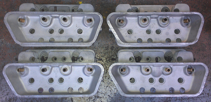
It turns out that there were not less than four valve guide and spring setups! I guess Porsche was a bit undecided in what worked best and fished around a bit. What this means is that one has to be very careful when servicing these heads because it's dangerous to assume that you know what any specific part is. In short, it makes it a completely custom job all around, seats and guides. And, as you have probably figured out by now, we always install new guids in every engine we rebuild, and we always change out the early seats for modern ones that stand up to modern (lead-free) gasoline.
To save on setup time / hassle, I did two pair at once - this engine will get one of these two pairs.
Therefore, new seats were installed all around. And, while at it, all new guides were installed, too. As noted above, that's very easily said, but very hard to do correctly! The specifications book lists three different setups from the two-piece case era, and none of the parts are readily available anyway. So, you have to carefully measure what system is presently installed - and this many years on, and with clear evidence that someone had been working on these heads and did not do a complete job, you cannot trust that all the guides or seats are of the same type! The valve guides and seats had to be made for these purposes "from scratch." (Pretty useful stuff, that scratch!)
BELOW: Two pair of 2 piece case Super heads, one pair of which is for this engine. Note the new guides. One pair has its new seats already partially ground, the others haven't been touched yet. Both pair have been flycut and one pair needed decking - the other didn't.
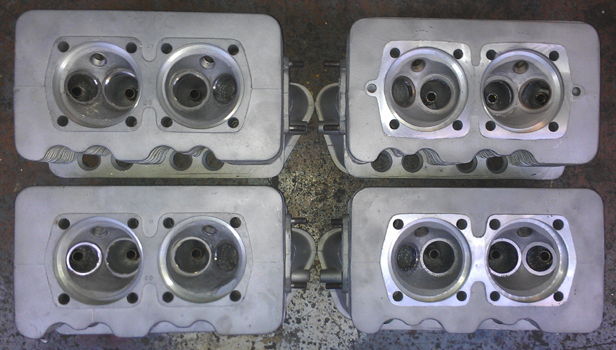
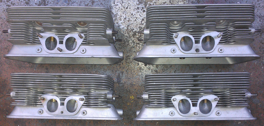
Now, we mount the heads...
Yes, on the left side in the image above, that's another two-piece Porsche engine that's following along behind this one! Look here for the ad / web page describing that one!
OK, time now to do a little more on the crankcase...
Oil pump, sump screen and cover, oil control piston - only took a few minutes.
Here it is as a longblock, minutes away from being ready for pickup or delivery - yeah, those are the wrong valve covers - will replace them when the paint dries on the right ones! Oops - decided NOT to paint the originals because I'm concerned that during preparations for painting that I risk getting sandblasting media into the vents that I can't get out.
Yes, the distributor drive shaft has not been installed because it should be left out until a distributor will be installed. Otherwise, if anyone rotates the engine backwards, the drive gear will ride up on the bronze crankshaft gear and may damage it....
NOTE: If this engine is sold as a long-block... One should NOT install the distributor drive gear without also installing a distributor because if anyone rotates the engine backwards, it will push the drive gear up where it can damage the bronze drive gear! Therefore, the distributor drive is NOT mounted until the last reasonable moment!
When you're ready for work on your machine, just let us know.
Because some people are keeping logs of VIN and engine numbers and then purport to tell people what someone else has, out of respect and concern for a buyer's privacy, exact VIN and engine number data are not published here.